• The move to the new server is done. There are some software and database maintenance updates in process. This has us passing the hat around to help out. We appreciate any donations. Seriously, even a dollar helps. The payment page may be found here - https://www.audiokarma.org/support.html

SX-737 Filter caps and Bleeder resistor

pa_200

Well-Known Member
Yes I know there is a lot of information around and more than 50% who make a recap on the SX-737 are going to change the filter caps as well.
BUT is it really necessary and if YES, will you have a really audible difference to the original filter caps?

My filter caps 6.800µf/ 50V look still good and have these values
No 1: 7.200µF 1.4 esr and 0.9 vlos
No 2: 8.170µF 9.4 esr and 0.9 vlos

What is your advice? And if I should change them, what about putting on some bleeder resistor as well.
But here comes the same question, is it necessary, recommended and if yes, which one?
I have already other filter caps in stock but the 6.800 have only 6.200µf, while my new 10.000 vary between 8.500 and 9.300µF.
Since the newer ones are smaller in diameter I will only change them if there is a good chance, that I will have an advantage.
My main concern is, not to but too much stress on the power supply with much higher µf like anything above 10.000.
Personal will rather prefer something between 6.800 and below 10.000, except you can recommend a perfect match for this lovely SX-737.
 
Last edited:
Register to hide this ad
Cap 2 has a ESR of 10 ohms? At what frequency? That's not good.

Replace them both, it'll cost what, $6? Who cares if you can hear it - do it for the peace of mind then at least.
Don't add a bleeder resistor, they didn't need one for 40 years and they don't need one now.
 
Bleed resistors. Pioneer typically used 3.3K 2W or 3W resistors to bleed the charge off the caps at power-down.

Some amps/receivers bleed the charge off nicely without them, and some need help, so the resistors are added. With few exceptions, if the original design used them I'd put them back if the caps are replaced. I keep a supply of 5.6K 3W resistors around just for this purpose.

I found this from Echowars and it sums it up perfectly.
What size are the originals? I'll help look for replacements from Mouser?
 
Original there are none connected. I like the upgrade with the flyback diode on the protection board what I have already done, so why not an upgrade with the Bleeder resistor, but only if it make sense and improves the liablity.
 
In the SX-737 bleed resistors aren't necessary. And they won't improve anything. You can go up to 10K uf @ 63v on the main filter caps with absolutely no problems (as long as they fit the original holes).
 
When I'm back from vacation I will try it and report back. But one question in before. The new caps have a “snap in mount“, what is a good and solid way to connect the wire, beside the option of soldering? Pictures whoud be great.
 
What's the difference between a resistor and a cap (film) between the filter cap POS/neg terminals? I did some reading on the filter cap bleeder cap and it got a bit exhausting. Some love it, some say it's not needed.
 
Two entirely different functions.

1. Film Cap bypassing the big storage cap is used to present a uniform low impedance to ground for AC signals.
IF there is an AC signal pushing back into the main cap, it's SUPPOSED to DISAPPEAR (be SHORTED out) into the low impedance to ground.
If it doesn't - it can get into places that CLEAN power is ASSUMED.
The main cap looks like a toilet paper roll, but it has INDUCTANCE in all those turns.
Various arguments can be made that the big capacitors are adequate for all frequency ranges, but when a film cap is added and enhances the operation - well, seeing is believing.
Why is a film cap special? It IS rolled too. BUT the (ones we use)'s side of each foil is exposed on the end (two ends, two foils, 2 connections) and it is all connected together.
https://en.wikipedia.org/wiki/Film_capacitor
A key advantage of modern film capacitor internal construction is direct contact to the electrodes on both ends of the winding. This contact keeps all current paths to the entire electrode very short. The setup behaves like a large number of individual capacitors connected in parallel, thus reducing the internal ohmic losses (ESR) and the parasitic inductance (ESL). The inherent geometry of film capacitor structure results in very low ohmic losses and a very low parasitic inductance, which makes them especially suitable for applications with very high surge currents (snubbers) and for AC power applications, or for applications at higher frequencies.

2. Bleeder RESISTOR: discharges the main cap continuously.
MY biggest like about permanently installed bleeders, is when power is turned off, the big caps are discharged FLAT and KEPT that way.
Without them, the output stages are expected to drain them, but somewhere along the shutdown sequence the output stages STOP operating and some charge remains, lurking to bite.

The most destructive consequences for me have been in the NSA amps, like the SX-3900 etc... during troubleshooting.
So as a personal consequence I carefully ADD bleeder resistors to those units.

The most disconcerting of the consequences of this I encountered with this was my old SX-636 unit. Remember that a SX-636 does NOT have a protect relay, otherwise weirdnesses in the power amp are caged into the circuitry and NOT unleashed upon speakers. Some time (minutes, hours etc) after turning OFF using just the power switch on my own SX-636, my speakers would erupt into thunderous random and prolonged violence and low level scratching. Now, attributing that to just the 2sc1451 transistors was incorrect. Now imagine being asleep a few hours before it decides to cut loose!! Not until I added the bleeders was it finally quieted.
 
Last edited:
So as a personal consequence I carefully ADD bleeder resistors to those units.

The most disconcerting of the consequences of this I encountered with this was my old SX-636 unit.
Really glad you take the time to explain some of these topics, your post above is very enlightening !!
I have had similar issues as you described above with my SX-636, mostly just a little "pop" after some time..... What size and wattage resistor did you use as a bleeder ??
 
Before switching the SX-737 to OFF, I always turn the volume down to zero. But I still get a loud popping noise over the speakers shortly after the power switch is down.
I thought the protection relay will prevent that.
Any idea how I can get rid of that plop?
 
Before switching the SX-737 to OFF, I always turn the volume down to zero. But I still get a loud popping noise over the speakers shortly after the power switch is down.
I thought the protection relay will prevent that.
Any idea how I can get rid of that plop?

Your protection circuit is probably not operating correctly.

Protection circuit failures are usually the most transparent, especially when the failure keeps the relay engaged.

If the protection does NOT disengage when AWR-057 F1 (3 amps) is pulled, the circuit is NOT working correctly.
 
I just pulled AWR-057 F1 and the unit is still running, Protection circuit has NOT disengaged!! But all the scale lamps are removed, just in case that information is needed.
 
Last edited:
Problem solved, was a typical self-made issue. Many thanks to the famous AK-Members!:thumbsup:
Three weeks before I have change all caps and transistor on that board according to the available list, but it was late and worked under stress.

After rechecking everything again, the mistake was found with false pinout on Q1, 3 and 6.

Changed all three again and double rechecked the pins. Now I have the following voltages
Cathode D5 = 18.8 vdc
Cathode D6 = 18.75 vdc
Cathode D7 = 18.75 vdc
With F1 pulled the relay does NOT click in. Protection should now work correct and the plopp is gone as well when powering off. :beerchug:
Anything else to recheck on that board just in case?
 
I found this from Echowars and it sums it up perfectly.
What size are the originals? I'll help look for replacements from Mouser?
Hello Bob, Did you ever find a filter cap for the 737, I'm having trouble locating 1 that size. Correct me if I'm wrong but is it 40mm x 60mm?
 
I will give you an answer and some pictures what and how I have them installed on my 737 tonight when I back from work.
One think I can tell already, you will have difficulties to find the wide diameter, all new ones are smaller. But I’m very pleased with the sound.
 
I’ve got two SX-737 on my desk, one is still original, and the other one is refurbished on nearly every board, according to the replacement list available here at AK.

My plan was to check if there is an audible difference between the original unit and the refurbished one. And I can tell, YES there is a positive difference on the redone unit, BUT so far I can’t exactly tell you, which part is responsible for the improvement, if not all together.

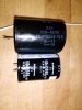
Back to the filter caps. The org. made by ELNA are 6.800µf/50V with 40mm diameter and 60mm height.

I had several Rubicon with snap in pins at home, size 10.000µf / 50V and selected a pair with similar values. The diameter is 35mm and the height is 50mm. These filter caps are probably second choise they hat only around 8.745µf which was good for me. I didn’t want to use bigger ones, to prevent too much stress on the power switch.
And I’m very happy with the sound, as I said, you can definitely hear a difference.
There are probably other caps available, or even better ones, so if someone has a better suggestion feel free to give me a link.

How did I install them!
You can still use the condenser clamp with a thick enough sealing tape around the smaller caps.

First before you unmount something, I strongly recommend to make a couple of picture and a short drawing with the wire color running to and from the caps.
I like to describe it a bit more, so everyone who need the information in the future can use it as well.

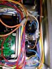
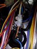
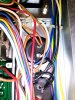
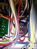
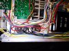
If you have the unit upside down and the power transformer on the right side, it’s the best way to start. From right to left you have first the two orange wire on the MINUS pin of the right cap. These orange wires, one goes to pin 10 on the power supply, the second one to pin 29 on the main amp.

On the PLUS pin of the right cap there is the white wire coming from the power transformer and a black wire going to the MINUS pin of the left filter cap. Another black cable from that left filter cap minus pin is connected to the next minus collection point.
The last pin on the left cap is again PLUS and here you have two red wires. One goes to pin 9 on the power supply, the second one to pin 32 on the main amp.
You can recheck it on the attached picture with the original caps.

The best way for me to use the snap in pins and to connect the caps with a bit more cable, I used uninsulated wire ferrules over the pins and soldered a 2 inch long cable into the ferrule. The plan was to have a flexible connection, so the best way for me was to connect all the other wires with terminal block connectors.

After you have changed the caps AND BEFORE you switch the main power on again, you are strongly advised to recheck all the wires twice. Then use a DBT on the first test, it will surly save you a lot of work and trouble.
Suggestions for improvement are always welcome.
IMG_20190912_130944.jpg IMG_20190912_131207.jpg IMG_20190912_131318.jpg IMG_20190912_172315.jpg IMG_20190912_172321.jpg IMG_20190912_172330.jpg
 
Last edited:
Back
Top Bottom