• The move to the new server is done. There are some software and database maintenance updates in process. This has us passing the hat around to help out. We appreciate any donations. Seriously, even a dollar helps. The payment page may be found here - https://www.audiokarma.org/support.html

SX-737 power amp AWH-033 issue, blown transistors

pa_200

Well-Known Member
I need some help on the power amp on my SX-737 after an unsuccessful renewal attempt.

What was done before!

I changed caps and transistors on the power supply, protection circuit, equalizer assembly and as last one the power amp.
All DC voltages have been good at the power supply and were even better after the renewal.

The receiver was running before I started the job, but now I probably have killed on the power amp at least the two 2sb530 (Q13-14).

I finished all caps, the four trimpotis and changed all the transistors Q1 until Q10. Only the 4 Output Q11 – Q14 I did not touch so far.

The q1 – q4, 2sa726 were replaced by SA992
The q5 + q6, 2sc1451 were replaced by SC3503
The q7 + q8, 2sd357 were replaced by SC2073
The q9 + q10, 2sb527 were replaced by SA940

First I powered up with the DBT for about one minute and everything looked great. Next I set it up accorting to the sm to check the bias and idle current, this time without DBT.

The trimpotis have been preadjusted to the old values I measured before.

It locked good as well in the beginning, only the idle current was above 200mV on both sides and I could not get it below 30mV. Even with the trimpotis turned fully left, which was very strange, it didn’t get lower.

Then an unexpected bang, now smoke or smell, so I switched power off to prevent further damage.

Without power I figured out, that the case of the two 2sb530 hat contact to ground. After a second recheck, I found one mistake, two caps mixed and installed at the wrong position. The C10 was in the position of C20 and vice versa. C9 and C19 are sitting in the correct place.

But could this be the reason for the shorted Q13 and 14?
And the other question, why did I have to turn trimpotis VR 3+4 fully left without achieving 0VDC?

The four caps are out again but according to the tester are still good. The same with both q9/10.

What I don’t understand, my tester shows no malfunction on the four output transistors q11-q14 but before I had on both sb530 contact between case/collector and ground.

Now I have all four outputs removed, but now clue what to check next and to carry on. Without knowing the reason for the kill, I wound install new outputs again.
 
Last edited:
Register to hide this ad
OK, back to basics.
The first thing I would do is verify all the components I replaced are correctly installed. Check that the right caps are in the right places and polarities on electrolytic caps are correct. Check that the correct transistors are installed with proper orientation, sometimes replacements have different lead positions. Leave the output transistors uninstalled for now. The trimpots for setting bias (VR1 and VR2) should be set to minimum resistance (0Ω), check with ohmmeter, sometimes replacements do not orient the same as the originals.
 
Last edited:
Ok I will recheck all the parts again. Might take until tomorrow, have to do some other priorities before.
As written in the first post, there was a mistake/ mix-up between c10 and c20. The VR1 and 2 have been set to a value of 50 ohm, and the VR3 and 4 were set around 4KOhm.

During power up I only moved the VR3/4 and now they are at minimum (zero ohm, fully left side)
Q7, 8, 9, 10 are out again and test good with the little LCR-T4 Mega328 Transistor Tester.

What I don’t understand right now, all four output transistors checked still good with solid hfe and mVolt. A crosscheck with two different DMM show as well now shortage between base, collector or emitter. If I’m lucky, they might still be OK. If necessary, I can post the values for them.
Maybe someone can explain why I could measure a connection to ground to the case/collector on both 2sb530 after the bang, but not before?
 
Ok I will recheck all the parts again. Might take until tomorrow, have to do some other priorities before.
As written in the first post, there was a mistake/ mix-up between c10 and c20. The VR1 and 2 have been set to a value of 50 ohm, and the VR3 and 4 were set around 4KOhm.

During power up I only moved the VR3/4 and now they are at minimum (zero ohm, fully left side)
Q7, 8, 9, 10 are out again and test good with the little LCR-T4 Mega328 Transistor Tester.

What I don’t understand right now, all four output transistors checked still good with solid hfe and mVolt. A crosscheck with two different DMM show as well now shortage between base, collector or emitter. If I’m lucky, they might still be OK. If necessary, I can post the values for them.
Maybe someone can explain why I could measure a connection to ground to the case/collector on both 2sb530 after the bang, but not before?
Don't worry about that now.
Let's take this step by step, and not bounce back and forth between past and present.
VR1 and VR2, the bias pots must be set to minimum (0Ω), VR3 and VR4 should be centered.
Do not put Q7, 8, 9, 10 back in yet, there is another test I want you to do that I don't have time to explain right now, have to run an errand.
 
That will probably the best approach to take it step by step. I’ll take all time necessary until we have a successful result. Giving up in between is not an option.
 
Last edited:
With the driver transistors out (Q7-10), this is a perfect opportunity to test the STV-4 diodes, D1 and D2 on the Power Amp Assy. AWH-033. Their job is to stabilize bias current as temperature rises, offsetting the increase current flow in the output transistors caused by heat.
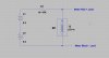
Build this little test jig, it uses one or two nine volt batteries, a 1kΩ to 10kΩ resistor (not a critical value) and some wire. Alligator clips may help keep it connected while you make voltage measurements.
STV_test.jpg
If you use 1 battery and a 1k resistor it will push about 6 to 7 mA of current through the STV4. Voltage polarity matters, connect just like the diagram shows. The meter should read between 2 and 3 vdc on a good STV. Post the voltage that you get for each STV-4.
I guess I should ask, do you want me to explain what I am looking for and why we are doing the tests? Some people want to know, some just want it fixed without complicating it with explanations. I am good either way, let me know. If you have a question please ask!
 
Last edited:
I definitely appreciate if you explain what you are looking for and why we are doing the tests. So please keep it that way, because I’m not an electronic expert and just start to build up a knowledge base.
I will build this little test jig with two nine volt batteries, hopeful I find a big resistor. If not I will connect a few inline.
I will write done in detail what I have built (even a picture will help extra), just to make sure you get the picture what I’m doing over here.
Can I take the measurement WITHOUT lifting the legs of d1 and d2?
 
Larry I only turned the VR3 and VR4 with the pin 3 and 17 against ground. I was aware of that screw up you explain in another thread, but it probably didn't prevent me from cracking one part. :dunno:

@merlynski
I’ve just done your recommended test.
For the test I used 2 x 9V blocks and got 17.4 Vdc, then a 2.2 K Ohm resistor was in the red line.

The leads of D1 and D2 have not been unsoldered and I used the DMM like given on the diagram.
D1 hat 0 vdc !!! and D2 had 2.2 vdc
Doesn’t look good for the D1 or ?

Edit!!
SORRY SORRY, everything back, my bad handwriting tricked me and I mixed it up with the picture of the foil side. The D1 is the good one and D2 is broken.
I have just rechecked it. If you lock on the topside, it is die STV sitting between pin 22 and 23.
 
Last edited:
I definitely appreciate if you explain what you are looking for and why we are doing the tests. So please keep it that way, because I’m not an electronic expert and just start to build up a knowledge base.
I will build this little test jig with two nine volt batteries, hopeful I find a big resistor. If not I will connect a few inline.
I will write done in detail what I have built (even a picture will help extra), just to make sure you get the picture what I’m doing over here.
Can I take the measurement WITHOUT lifting the legs of d1 and d2?
Yes you can, because the driver transistors are removed (Q7-10) there is less of an alternate current path to cause an improper reading. If you use two batteries in the build use a 2kΩ or 2.2kΩ resistor. The purpose of the test jig is to forward bias the 4 pn junctions in the STV-4 to see if they are good or bad. Most DMMs that have a diode test mode do not have enough voltage to drive 4 pn junctions (or zener diodes). You can also use it to test any pn junction and even zener diodes up to about 15vdc. If you want to test higher voltage zeners add more batteries to increase the voltage.

The MANUAL IS BACKWARDS With regard to the operation of the TRIMPOTS! See this thread.............. https://audiokarma.org/forums/index.php?threads/notice-to-all-new-sx-737-or-7730-owners.464083/
Thanks Larry, I was going by the schematic, though I had seen that error in the SM before it is well worth repeating.

[
@merlynski
I’ve just done your recommended test.
For the test I used 2 x 9V blocks and got 17.4 Vdc, then a 2.2 K Ohm resistor was in the red line.

The leads of D1 and D2 have not been unsoldered and I used the DMM like given on the diagram.
D1 hat 0 vdc !!! and D2 had 2.2 vdc
Doesn’t look good for the D1 or ?[/QUOTE]

You are correct, D1 looks shorted, lift one leg to retest, just to be sure. If it tests good out of circuit look for other bad components and/or solder bridges in that area. D2 looks fine.
 
D1 is out of curcuit with both legs, with the test jig it still reads 0 vdc!
All other parts have been rechecked for correct pin and polarity.
What would happen if I change the polarity between the test jig and the STV-4 just for measurement?
 
Last edited:
D1 is out of curcuit with both legs, with the test jig it still reads 0 vdc!
All other parts have been rechecked for correct pin and polarity.
It is bad. You will have to replace it. Do you have another one? We can continue without it for now but will need it soon.

Next step, with the driver and output transistors still out, is to verify power supplies' voltages on DBT. Plug the Receiver into the DBT and power up. If the bulb flashes bright, then dims down, measure voltages. If it stays bright, power off, we need to check further. Meter black lead to ground (chassis).
Some of the voltages will be lower than schematic indicates while on DBT, that is OK for now.
On the power supply board AWR-057 check the following pins:
Pin 2, should be about 7vac
Pin 9, sb about +33vdc
Pin 10, sb about -33vdc
Pins 12 & 13, sb about -13vdc
Pin 14, sb about +35vdc
Pin 15 & 16, sb about +30vdc
Pin 17, sb about +23vdc
Pins 19 & 20, sb about +13vdc.
Pin 18, 0v (ground)
 
What would happen if I change the polarity between the test jig and the STV-4 just for measurement?
Reverse bias checks diodes for leakage, or zeners for zener voltage. A good rectifier will measure the same as the battery voltage, or very close, because there is very little current flowing. An STV is not used as a rectifier and may appear quite leaky, but this is not necessarily a failure, because it is always forward biased in use. Your bad one will probably still show 0v when reverse biased (shorted).
 
Reverse bias checks diodes for leakage, or zeners for zener voltage. A good rectifier will measure the same as the battery voltage, or very close, because there is very little current flowing. An STV is not used as a rectifier and may appear quite leaky, but this is not necessarily a failure, because it is always forward biased in use. Your bad one will probably still show 0v when reverse biased (shorted).
When I measure it reverse, then I have the full voltage of the two batteries with about 17 Vdc
 
Unfortunatelly I have no spare STV
Pin 2, should be about 7vac
Pin 9, sb about +33vdc
Pin 10, sb about -33vdc
Pins 12 & 13, sb about -13vdc
Pin 14, sb about +35vdc
Pin 15 & 16, sb about +30vdc
Pin 17, sb about +23vdc
Pins 19 & 20, sb about +13vdc.
Pin 18, 0v (ground)

The DBT works good, dims down. Voltage out of the wall 230Vac, voltage selector set to 240V.
Power supply board has been rebuilt before.
All follwing voltages measured with DBT on!
Pin 2, 7.3 vac
Pin 9, +32.1 vdc
Pin 10, -32.1 vdc
Pins 12 & 13, -12.8 vdc
Pin 14, +33.8 vdc
Pin 15 & 16, +29.8 vdc
Pin 17, +22.8 vdc
Pins 19 & 20, +12.6 vdc.
Pin 18, 0v good ground contact
 
When I measure it reverse, then I have the full voltage of the two batteries with about 17 Vdc
What meter voltage range were you on when you tested forward bias? With reverse bias even one good diode junction will block current flow, but it needs 4 good pn junction voltage drops to work properly in the circuit. 4 times 0.6vdc is 2.4vdc, lower current may have slightly lower junction voltage, 2 to 3 vdc is a good test result. When we get to functional testing we will compare D1 and D2 in circuit with the power on (not on test jig).
 
What meter voltage range were you on when you tested forward bias? With reverse bias even one good diode junction will block current flow, but it needs 4 good pn junction voltage drops to work properly in the circuit. 4 times 0.6vdc is 2.4vdc, lower current may have slightly lower junction voltage, 2 to 3 vdc is a good test result. When we get to functional testing we will compare D1 and D2 in circuit with the power on (not on test jig).
The DMM was set to 20 VDC. Just again to make it clear.
Red lead on anode and black on cathode side shows 0 Vdc. Black lead on anode and red on cathode gives me 17 Vdc.
 
Unfortunatelly I have no spare STV


The DBT works good, dims down. Voltage out of the wall 230Vac, voltage selector set to 240V.
Power supply board has been rebuilt before.
All follwing voltages measured with DBT on!
Pin 2, 7.3 vac
Pin 9, +32.1 vdc
Pin 10, -32.1 vdc
Pins 12 & 13, -12.8 vdc
Pin 14, +33.8 vdc
Pin 15 & 16, +29.8 vdc
Pin 17, +22.8 vdc
Pins 19 & 20, +12.6 vdc.
Pin 18, 0v good ground contact

Those look excellent to me. I saw in other threads you had rebuilt the PS, I wanted to verify nothing had gone bad.
Do you have a source for another STV-4? We can do more testing on the channel with the good one while waiting for it, but they are hard to find.

The DMM was set to 20 VDC. Just again to make it clear.
Red lead on anode and black on cathode side shows 0 Vdc. Black lead on anode and red on cathode gives me 17 Vdc.
Yes it is bad :(. I would not trust the transistors that were in that side around it, I would replace them (again?), Q5, 7, 9, as well as Q11 & 13 when we get ready to reinstall output transistors..
 
So far I can't find a source for another STV-4 but I found a thread how to rebuild one with 4 times 1N4148's.
Maybe some other member has got another workaround on hand.
 
So far I can't find a source for another STV-4 but I found a thread how to rebuild one with 4 times 1N4148's.
Maybe some other member has got another workaround on hand.
I have seen several threads here on AK about that option.
 
Back
Top Bottom