• The move to the new server is done. There are some software and database maintenance updates in process. This has us passing the hat around to help out. We appreciate any donations. Seriously, even a dollar helps. The payment page may be found here - https://www.audiokarma.org/support.html

SX-737 Problem with short circuit, help needed

pa_200

Well-Known Member
Started on Sunday my planed SX-737 recap project, hoped everything will go well, but it didn’t! Now I need some ideas and help.

Let’s start step by step.

It’s a 220V GN Modell with an AWR-057 power supply. First test on DBT went well, bulb dimmed an it played music with tuner selected, nobody worked on it before.
I will make a full recap and swap most of the old transistors.
With the power for one hour unplugged, I started with the AWR-057 as first board. While trying to loosen the lines and removing them from the retainers, suddenly I produced a spark :( in the area of pin 11 – 9.
My mistake :thumbsdown:, because I expected the big filter caps had already bleeded and didn’t recheck that or discharged them, just to be sure.

So continued with the change of all electrolytic and the four Transistors.
  • Both SD313 where replaced by KSC2072, same pinout as the old ones
  • Both SC945 where replaced by KSC2383, same pinout as the old ones
  • All Caps and transistors were several times rechecked for the correct pins, just to be on the save side.

But I have to admit, this board is really hard to work on, especially on the area of pin 12 -21.
The first test was again with the DBT, but this time, the bulb stays bright….Sh...

As next, I removed all four outputs Q11-14 from AWH-033 and both STV-4 to protect them from potential damage.

Second test again with the DBT, and still the bulb stays bright….:dunno:

Tried with my little knowledge to isolate the problem I expect going from pins 9-11 to the other boards, but no success.

Now compared that AWH-057 with my second 737 working unit and measured the resistance from every pin to chassis ground, hoping to find the cause, but wasn’t successful so far.

The unit was not connected to power after the second DBT test for any testing.

I don’t want to continue with the protection board, as long that short circuit is not solved.

Tried to find the issue by myself, but now I hope for some ideas and every help is welcome to bring this lovely receiver back to life.
 
Register to hide this ad
I tested D1-D4 already with a diode tester, but still all installed. Got OL on all four from anode to cathode and around 0,470 V from cathode to anode. Can lift one leg if that will help.

As I mentioned above, I compared all measurements with the second working SX-737, looking for some difference, but didn’t find any.
 
:lurk:
You'll find it!
Not that it would matter for your troubleshooting necessarily but I am curious why you are not replacing the diodes on AWR-057 with new ones, since you're rebuilding AWR-057.
This what I had planned for my SX-737, when I ever have time to work on it:
D1 SR3AM-4 863-1N5404G
D2 SR3AM-4 863-1N5404G
D3 SR3AM-4 863-1N5404G
D4 SR3AM-4 863-1N5404G
D5 S1B01-02 863-1N4004G
D6 S1B01-02 863-1N4004G
D7 S1B01-02 863-1N4004G
D8 Zener WZ-130 512-1N5243B
D9 Zener WZ-140 512-1N5244B

Seems like a good practice to get rid of those old ones for preventive reasons?
 
I have new diodes available, but this board has very bad and unstable traces and I already lifted some pads while desoldering. So at this stage, I would prefer only to swap the identified bad parts.
Never had so much problems with desoldering like on this board.
 
Pulled D1 – D4 today, all 4 checked good, but I definitely have to improve my desoldering skills. Was quite a job to get them out.

Replaced them with 1N 5404 and had a first check on DBT. Slight change but not a real improvement.
Bulb went bright, then dim and back to some medium brightness.

The reason for the short circuit is still present and hiding somewhere!! Any other Idea where to search?
 
Last edited:
While on the DBT measure DCV on pin 8 9 and pin 10 of the power supply board. They should be about equal voltages, but one positive and one negative. If one is much lower than the other that is probably the supply with the problem. Probably about 30 to 35vdc on DBT for a good supply. If both are good the problem is elsewhere.
EDIT: correct pin number
 
Last edited:
@ fromnowon. Since it was a bit quiet around this thread, I still had to move on and would like to keep everyone interested up to date. One thing first, some little steps forward, but didn’t find the culprit yet.

For the test I use a 60Watt bulb. ALL tests I mention here, are still done with the 60W DBT in line!!

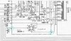
After finishing the AWR-057 Power Supply I tried to narrow down to the bad area. So some study of the Schematic Diagram page 27/28 was necessary.

To isolate the 6 Power lines (pin 1, 3, 4, 6, 8, 11) coming from the transformer, I pulled the four Fuses F1-F4 (going to pin1, 3, 4, 6). Pin 8 + 11 are direct (unfused) connected.

With F1-F4 lifted the bulb stayed dimmed, so I expect the area behind Pin 8 + 11 is working fine.
Then plugged in only one Fuse at a time. With F1 and F4 connected, the bulb stayed dimmed as well.
So the bad area must be behind F2 and F3, with each fuse plugged in, the bulb still glows.

Together with the second good SX-737 I made lots of measurements and while doing so, there was some light smoke coming out of the area around the Power Amp. Switched it off immediately hoping to see/find the hot part, BUT was unable the locate one.

With this in mind, I continued replacing to old caps and transistors first with the AWM-025 Protection Board, then AWF-011 Equalizer Amp and now the AWG-030 Control Amp.

I expect the short circuit in the Power amp area, since none of the boards I have done, had a real broken part.
Will finish all the other boards first, before moving on to the Power Amp as last one.
 
Last edited:
While on the DBT measure DCV on pin 8 and pin 10 of the power supply board. They should be about equal voltages, but one positive and one negative. If one is much lower than the other that is probably the supply with the problem. Probably about 30 to 35vdc on DBT for a good supply. If both are good the problem is elsewhere.

Just to be correct and stay on the safe side. The numbers on the Schematic Diagram are a bit blurred, but page 54 has got a better print. If I read the Schematic correct, pin 8 and 11 go to the transformer and should carry AC while pin 9 and 10 should be on the DC side.

To give you a full information, here are all voltages for pin 8, 9, 10 and 11 of the power supply board.

DBT connected and F1-4 plugged in
Pin 8: 18,8 ACV, zero DCV
Pin 9: zero ACV, +20,3 DCV
Pin 10: zero ACV, -21,0 DCV
Pin 11: 19,2 ACV, zero DCV

This time with DBT connected, F2+3 lifted, F1 plus F4 plugged in
Pin 8: 26,3 ACV, zero DCV
Pin 9: zero ACV, +36,3 DCV
Pin 10: zero ACV, -36,3 DCV
Pin 11: 26,2 ACV, zero DCV

Edit: Don’t forget, Q11 – Q14 and both STV4H are still removed from the Power Amplifier AWH-033
 
Last edited:
The good part on this, one can easily follow and identify the line to the transformer. So it's 8 and 11 on the AC side, 9 and 10 on the DC side.
 
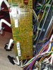
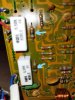
Quick update for you. Compared the picture of the AWH-033 board taken in the beginning and how it looks now. There is some color on all four resistors R23 – R26, but they still have the 150 ohm. As a novice I still have no clue what exactly could be the issue for that.

Will start to pull all caps and transistor I planned to replace and report back.
 
Last edited:
The label for pin 9 was smudged on my schematic, looked like 8.

So the bad area must be behind F2 and F3, with each fuse plugged in, the bulb still glows.
I concur. Verify C7 (1000µF, 50V) is oriented correctly and not leaky. Also C17, (22µF, 25v).
Measure DCV on pin 14, if good it should be about +30vdc on DBT.
You can pull and test Q1 and Q2. While Q1 is out, put F2, F3 back in and check on DBT again. Replacement for Q1 sb KSC2073, Q2 sb KSC1845 (if you have one).
 
The AWK-057 Power Supply is already rebuilt with all caps and transistors. Pin 14 has +34,6 DCV on DBT.

Before, the bulb stayed on with fuse 2 and 3 plugged in and the AWK-033 Power Amp had only the Q11 – Q14 and both STV4H are removed.

NOW I worked on the Power Amp and pulled all old caps, the four trim pots and all transistors. With this parts removed the bulb stayed dimmed, even with all fuses plugged in.
Tested all transistors, none of them was bad or way off. Only some of the caps were out of tolerance, especially the sky blue Sanyo’s.

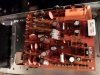
As you can see on the picture, the four 150 ohm resistors R23 – R26 picked up some heat.

Big question, what was the cause for the heat issue?
Can I start already with the rebuild or should I first check some other parts?

IMG_20211119_213516.jpg IMG_20211119_213604.jpg IMG_20211119_213622_LI.jpg
 
Last edited:
Big question, what was the cause for the heat issue?

If the output transistors are removed and the STV4s removed the voltage across those resistors can increase excessively, because the STV4 is not present to limit the voltage across the bias spreader transistor's (drivers) bases: Q7, Q9 and Q8, Q10 will saturate, current will flow and those resistors will overheat. That may have also been the cause of your bright DBT. I would put in new transistors for Q7 - Q10 and reinstall the STV4s and new bias VR1 and VR2 (set to minimum) before powering up again on DBT.
 
Thanks merlynski for the info.

I have ordered new 150ohm resistors and plan a full replacement of all electrolytic and transistors except the Q11-Q16.

The 2SA763 will be replaced with KSA992 and the 2SC1451 with KSC3503.
But what about the 2SB527 and 2SB357?
The available information shows as replacement KSC2690AYS or KSC2073tu for the 2SC357 and the KSA1220AYS or KSA940tu for the 2SB527

To get the best sound with this unit what is your advice and experience? Keep the old ones or replace with one set of the newer ones? I have still the old transistors and all four newer types available.

And what about the heatsink on a TO 126 transistor in the position for Q7 – Q10? TO 126 are difficult to mount on the original heatsink.
 
Last edited:
I have never had my hands on an SX-737 . . .
I would not replace a TO-220 with a TO-126, use the KSC2073 and the KSA940.
 
hi @pa_200
In case it helps, here is the list I've been keeping for my eventual project, for AWH-033 transistors. Based on other threads.
I hope it's right - if it's different than what Merlynski is recommending then I'm not confident.
Curious what you'll end up using.
AWH-033 trans.JPG
 
Back
Top Bottom