• The move to the new server is done. There are some software and database maintenance updates in process. This has us passing the hat around to help out. We appreciate any donations. Seriously, even a dollar helps. The payment page may be found here - https://www.audiokarma.org/support.html

SX-750 Bulb Trouble

theiceberg

Active Member
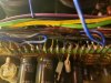
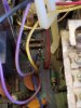
Hello, we are working on a restoration of our old Pioneer after decades of sitting in a hot California shed, and it of course needs a fair bit of love to get it back in decent shape. We noticed 6 of the 9 bulbs were burned out when plugged in, so we ordered the modern set of appropriate bulbs from Dave (dgwojo). The 3 backlight lamps were bad, as were the FM, Phono, and Stereo bulbs. Excited to get working, I got the 3 backlight lamps in and working correctly, but stupidly moved onto the Stereo/Power set and cut all 4 blue wires (not touching wire wraps) without tagging them. In addition to this I crossed two exposed lamp wires and blew the FU1 fuse (replaced since). Upon referencing the service manual, these bulbs are I believe referenced as PL4 and PL5. I have spent a fair bit of time mixing and matching the bulb wires, but the best I am able to do is get one fully lit, and the other barely squeaking light out. With some trial and error, it seems that the 23 wire is pretty much drawing nothing, as no combination of wiring the other three is emitting a response. I have done a surface level testing of a wire bypass straight to the post, but it's fairly tough to test and I feel my time is better spent seeking someone with knowledge of possible solutions. Any ideas of what to do from here? I appreciate it.
Ryan
 
Register to hide this ad
Look on pages 59 & 68 of the service manual . The foil side diagrams . Trace the wires in question on your SX 450 ,make note of there destinations and find them on the diagrams . AUX uses two gray wires on mine , one to pin#8 on tuner board , the other to pin #21 (ground) on power supply.
 
The dial illumination lamps are fed from Pins 13/14 on the power supply board (AWR-099). The power indicator lamp is fed from Pin 15 on that board.

The RF/AF board (AWE-073) supplies power to the function lamps. Pin 5 supplies the AM indicator, Pin 6 supplies the FM indicator, Pin 7 supplies the PHONO indicator, and Pin 8 supplies the AUX indicator.

All those lamps are grounded to a chassis ground.

The STEREO indicator is supplied by Pin 22 on the power supply/protection board (AWR-099), and is grouded through Pin 24 on the RF/AF board (AWE-073).
 
Thanks so much for the response. I have rewired using this guide, but I'm running into the same problem as before. The Power light is clear, but the rest are not responsive. Since starting working on this, the entire set of four bulbs have gone out, which to me indicates more than simply the bulbs are shot. I have checked around and can follow most of the ground wires back to the chassis, but I am not seeing anything clearly that would be cutting power to these bulbs. Is there a central spot to check that would connect the power of all of these bulbs together? I'll attach some pictures of whats going on, but they likely aren't much help.
 

Attachments

  • 20200711_201034.jpg
    20200711_201034.jpg
    112.4 KB · Views: 33
  • 20200711_201235.jpg
    20200711_201235.jpg
    88.3 KB · Views: 32
  • 20200711_100222.jpg
    20200711_100222.jpg
    96.8 KB · Views: 31
So I am continuing to look this unit over, and things are simply not adding up. I can follow the foil diagrams, and trace the wires back, but no posts look damaged, and the power light continues to be the only light working outside of the dial lamps. This unit will have a recap done in the near future, is it possible that a capacitor has died on the power supply board, killing power to these bulbs? What is curious to me is when this machine was being regularly used long ago, it was noted that bulbs were eventually going out over time, but they are not behaving properly for a simple bulb replacement. I will continue to look this over, but I am leaning towards a more thorough inspection during the recap job.
 
The usual progression is to repair, then recap. It can help avoid further confusion.

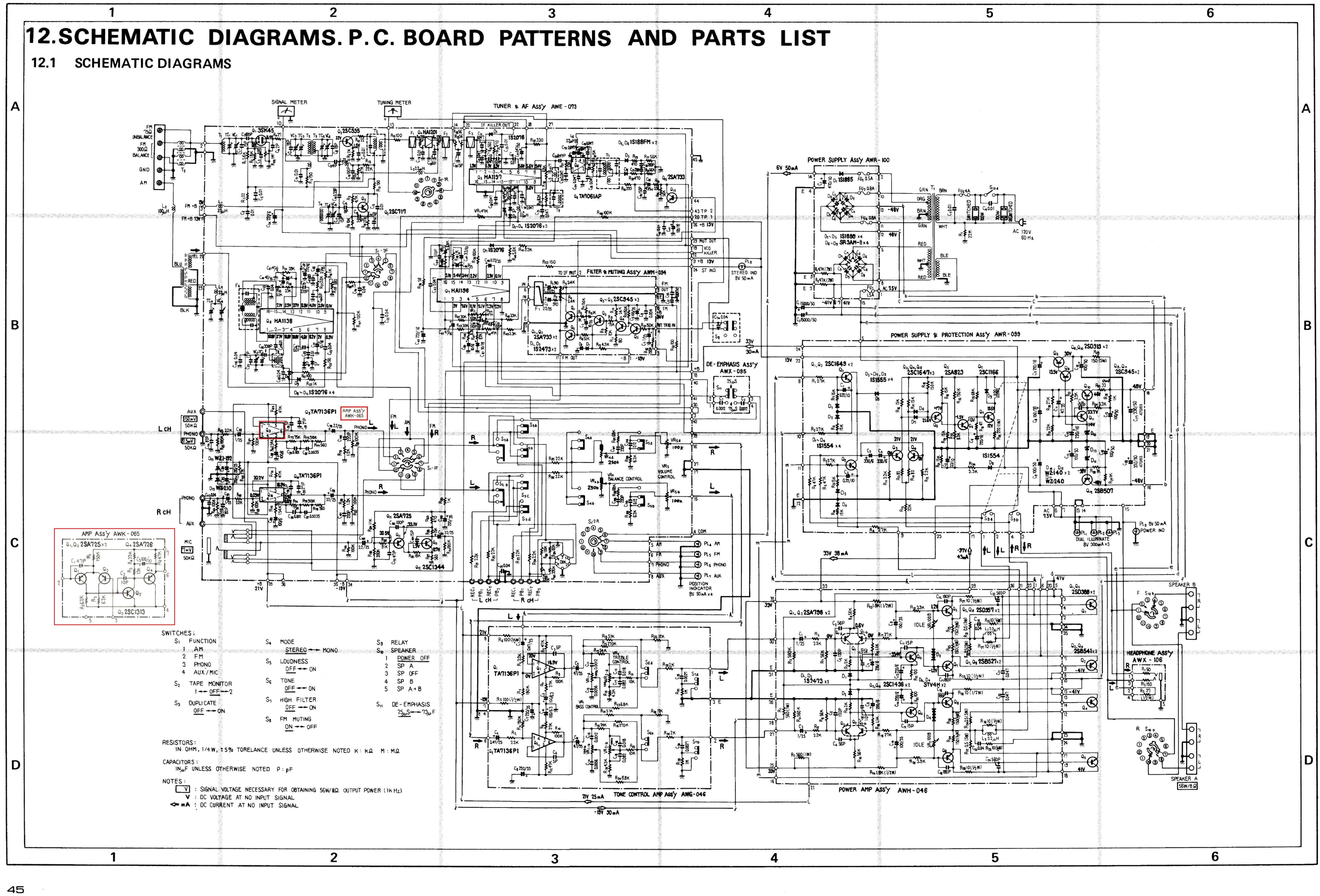
This may be helpful:

SX-750KC-KUSchematic.jpg
 
Last edited:
This is becoming quite interesting. I have neglected to check the audio behavior of the unit up until this point and am getting a little more to work with to uncover whats going on in the circuits here. With either testing FM static or a record through RCA phono, the machine will buzz loudly, go silent, relay sets, audio/static will play, relay clicks off, back to silence, and continue this loop indefinitely, all said and done completing this cycle in about a second or two. Calling back what intrusive work I have done, I have cut the bulb wires and reconnected new ones, replaced blown fuse, pulled transformer out quite a bit to fish out screws that dropped underneath it (concerned with possible wire damage tied to transformer due to pulling on it, but no wires appear damaged). The fuse concerns me, as the FU1 fuse calls for 1.5A through it, but scrambling through retail electronics has only yielded me a 1A and 2A set, so I am using 1A to better protect the unit (hopefully this is not a source of these problems).
 
It is certainly time to get my multi-meter out, it has been stowed away but I will go and search for it now and begin testing the voltages, I'll check 14 asap and post it.
 
Alright, tested both the lamps and the pins. Lamps all work ok, pins not so sure.
Pin 5: 7.1V
Pin 8: 0.1V
Pin 10: 0.0V
Pin 11: 0.0V
Note: The 22-24 pin loop that powers the stereo bulb also reads 0.0V.
 
That's a bad sign. Just as a double-check, please report the voltages between Pins 5&8 and Pins 10&11. 5-8 should read about 65VAC and 10-11 should read about 76VAC. If the voltages across those points are close to the spec, check the grounding for the center tap leads from the transformer secondaries.
 
I see. Yes, double checking between 5-8 gives about 6.7V, and between 10-11 is giving ~0.0. In regards to the transformer, I am not familiar with the grounding for center tap leads. I will flip it over and give the transformer wiring a look to see if I can see what you mean.
 
BfQ7dSmFvCJne6ox7
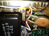
Alright, now I'm definitely in trouble. I read two wires via the multimeter from the transformer, and got about 67V or so from the brown wire, and 45.5 from the white wire. Linking the wires I'm talking about. However, upon removal of the multimeter from the white wire post & arbitrary chassis ground, power to the machine gave out, and it will no longer power on, with no fuses blown. Seems something quite bad happened, but there is no evidence to what specifically. This is what I have so far.
 

Attachments

  • I20200714_212055_LI.jpg
    I20200714_212055_LI.jpg
    117.6 KB · Views: 15
Frantic updates: I was incorrect in the power failing. Upon checking all fuse power inlets, all are getting fair voltages, and soon enough the lights powered back up- the FU1 fuse holder is loose and broke the circuit. Will have to bend that back into shape, but fortunately nothing has blown up.
 
It may also be prudent to check the solder connections at the fuse holders. If it is necessary to resolder them to establish good connections, remove the fuses first.
 
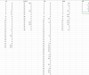
Ok, I made a few errors in reporting voltages yesterday, so the data I believe will be represented differently than how it appeared yesterday. I believe I was looking at the wrong board yesterday, so the pins at 5,8,10,11 should be different than reported. We went ahead and checked pretty much every board and marked the voltages through every pin we could find. The solder for the fuse holders looks good, and it seems that board all pulling power ok to each set of fuses.
 

Attachments

  • SX-750 Voltages.png
    SX-750 Voltages.png
    252.9 KB · Views: 16
Back
Top Bottom