

You are using an out of date browser. It may not display this or other websites correctly.
You should upgrade or use an alternative browser.
You should upgrade or use an alternative browser.
SX-750 Bulb Trouble
- Thread starter theiceberg
- Start date

theiceberg
Active Member
Alright, definitely more headway today. I did the research on that stereo bulb, and I understand how that's supposed to work, so I am not concerned with its function for the time being. I don't have any numbers today, but I went out and bought the necessary 1/8 to 1/4 adapter that I seem to have misplaced to use some monitors instead of the two bookshelf speakers that were being used previously. Also all bulbs have been soldered and shrink-wrapped and all (minus stereo) are working well. What I don't understand now is what is happening when using headphones. As was with the speakers, all channels give a pretty significant buzz, which is fine and will hopefully be resolved with more recapping done. But now ALL channels are working, IE the relay is not failing. Before, FM and records through Phono set the relay and failed, but with headphones audio can continuously play without a hitch. This looks like good news, but the speakers are intended as the main audio drivers for this, and getting those working will be the goal. The ancient speaker wire is being replaced in the next few days, but it doesn't seem likely that this would change the relay overload. Up next is checking boards 100, 099, and 073 at each pin and resistor for failure, but that is for tomorrow.

The audio buzz you hear in all modes is likely poorly filtered power making its way through the AF sections. That alone can trigger the protection circuit. Now that the lighting is mostly resolved, and before changing ANYTHING else, more voltage measurements would be helpful.
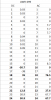
Primary focus will be on the AWR-099 board, standing on edge right in the middle of the unit. Test and record the DC voltages at Pins 16, 18, 22, and 24. Then set your meter to a low AC voltage range to retest and record the AC voltages at those pins. The results could be very revealing.
Primary focus will be on the AWR-099 board, standing on edge right in the middle of the unit. Test and record the DC voltages at Pins 16, 18, 22, and 24. Then set your meter to a low AC voltage range to retest and record the AC voltages at those pins. The results could be very revealing.
theiceberg
Active Member
theiceberg
Active Member

Test diodes D3 and D5 on the AWR-100 board, power off, both forward and reverse voltage drops. Testing in-circuit should be sufficient for now.
On second thought, check all those diodes forward and reverse. If you find any failed, a 1N4003 or better (1N4003-4007) would be acceptable replacements.
On second thought, check all those diodes forward and reverse. If you find any failed, a 1N4003 or better (1N4003-4007) would be acceptable replacements.
Last edited:
theiceberg
Active Member
Cool, just checked all the diodes on the 100 board. Not sure what to think here. All of them on the board are working as they should, closed where they are supposed to be, and current is flowing as is noted in the foil diagram. Except for the one that was replaced. Reading 17 on the multimeter forward and reverse. Disappointed, going to put the old one back in tomorrow, which upon checking behaves as the other ones of the same model already installed, so all the diodes should be working, at least by tomorrow.
theiceberg
Active Member
Actually I'm a bit more concerned. Tested the other diodes (ordered a set of 100) and they all behave the same as the ones installed that work on the power supply board. ~600 forward, open reverse. So the one installed SHOULD be behaving correctly, but instead its close to zero both forward and reverse. Still going to look at the original diode re-installed, but if it behaves poorly as well, I am not sure what to think.
theiceberg
Active Member
It appears as though the problems with this machine has migrated a bit since starting on it. I check the diodes, caps and pins on the 100 board and all seems well. I switched to the original diode and tested it as arranged in the foil diagram, and everything sounded good, even on one of the bookshelf speakers! Humming was low, protection circuit in check. But the 4 function lights were all getting 0V. So I took another new diode and installed it, and on the board the multimeter seems to dislike both forward and reverse readings, but I checked anyway. Low hum, FM and Phono record play without relay issues, AND the function lights work. So this seems to be in working order, and I'm sure there's an explanation, but I don't have one. However, there is still a relay issue, and I'm able to recreate it very consistently. With two bookshelf speakers in, at low volume, middle balance, the protection circuit will not activate. Note: one speaker plays very clearly, but the other one is a fraction of the volume, even when giving it full balance. Once the volume is raised with the balance either middle or skewed towards the weak speaker, protection circuit activates. When that problem speaker is cut even just by balance knob, volume can be put very high to the clear speaker with no problems. Both speaker boxes had their middle 8" speakers replaced with 8 ohm 225W ones, as the old ones were shot. With light research, this unit should be able to drive two 8 ohm speakers without overload, so this is the main problem before moving on to fixing the hum.
theiceberg
Active Member
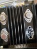
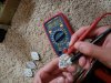
I was able to look into the output transistors, and got them all uninstalled and tested. I'm not 100% positive the readings are correct, but they all seem to behave the same, pictures included. If the error is somewhere in the driver, which I assume is the housing that the two transistor leads slot into, how are those accessed and tested? I'd think to start pulling them out from the underside where the wires lead to, but just have to be sure first.
Attachments

theiceberg
Active Member
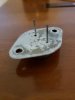
Alright, I'll use that method to test the transistors for sure, but I can't really test these specific ones in that way, as they don't have the 3 base, emitter collector leads, these only have 2. Testing these leads with the diode setting though, getting 550 for all in one direction and open circuit for the other direction, so I am still thinking these are not the problem. Still need to figure out what to look for on the drivers, two of them can easily be tested from the top, but the bottom two need to be removed from the unit to test, and its rigid enough for me to hesitate in just pulling on them, but I'll continue to work on it.
Attachments

theiceberg
Active Member
Oh really, alright I'll recheck it with that in mind, thanks.
theiceberg
Active Member
Well, it seems that something is indeed wrong with two of these transistors. While the diode readings seem to align across all four, in testing the ohms across all of them, one each of 2SD388 and 2SB541 are reading differently (specifically in the collector and emitter connection) when comparing to their counterparts. So I think going ahead and replacing these is a good idea. Looking online, it looks like I can buy original direct replacements for both of these, but it seems a bit cost ineffective if there are newer equivalent replacements out there somewhere. Is there a general recommendation for which to buy for both of these? Also, still not 100% sure on what to do with the transistor drivers, but this is a good start.
theiceberg
Active Member
Actually, it looks like the MJ15023/MJ15024 set is the way to go, right? I'll look into getting a set of these.
theiceberg
Active Member
It seems that you can find reproduction for the two original transistors fairly easily, so its probably smart to just get a set of these. We'll see in a few days if this is a good idea or not.
Those OnSemi TO-3 devices are good choices. Another opton is the NJW0821G abd compliment. It only requires a little creativity in the installation. However, it would be good to check the drivers so that new replacement outputs don't go up in smoke as soon as the unit is powered on.