

Bought a (another) SX-770. This is another one that should probably have been put out to pasture, but I love a challenge.
I broke my own rules on this one. I started with repairing the wooden cover (that should be last)
Put it on the DIM bulb, seemed ok, played music through Aux, but only left channel worked. Ass-u-me'd it was dirty controls.
Moved on to the lamps because only one was working. Another step in error.
Finally got back to testing. Cleaned all the pots, switches etc. Still no right channel. Osilliscope lead me to the main amp. Fuses were good. Clipped all the leads and pulled it out.
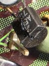
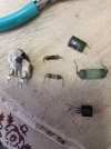
Found several burned components, but the board is ok.
Two of the power transistors were toast and I think they are either EOL or exspensive. I saw a snippet where someone replaced the originals with TIP41C's (which I had in inventory), totally different foot print.
So, I did a little modification to the heatsink, drilled the holes for the leads larger, drilled the mounting holes on the TIP41C's larger so I could used the existing mounting hardware and insulators.
Broke off the collector leads. Collectors are now connected through the "insulated from the heatsink" mounting bolts in the same manner as the originals.
Added heat shrink to protect the leads from the now enlarged pass through holes in the heatsink.
The one thing I missed was that two of the original transistor's collectors connected to the board by the top screws and two used the bottom screws, since I was only using the top screws, I had to run two jumpers.
Now before anyone gets upset that I'm butchering a classic receiver, note that this thing is in really bad shape. Bunch of corrosion all over the chassis. This is more of a science, proof of concept, project.
Waiting on the replacements for the burned up parts that I don't have.
I'm hoping it works once it's all back together. If I had it to do over, it might just be a donor.
I broke my own rules on this one. I started with repairing the wooden cover (that should be last)
Put it on the DIM bulb, seemed ok, played music through Aux, but only left channel worked. Ass-u-me'd it was dirty controls.
Moved on to the lamps because only one was working. Another step in error.
Finally got back to testing. Cleaned all the pots, switches etc. Still no right channel. Osilliscope lead me to the main amp. Fuses were good. Clipped all the leads and pulled it out.
Found several burned components, but the board is ok.
Two of the power transistors were toast and I think they are either EOL or exspensive. I saw a snippet where someone replaced the originals with TIP41C's (which I had in inventory), totally different foot print.
So, I did a little modification to the heatsink, drilled the holes for the leads larger, drilled the mounting holes on the TIP41C's larger so I could used the existing mounting hardware and insulators.
Broke off the collector leads. Collectors are now connected through the "insulated from the heatsink" mounting bolts in the same manner as the originals.
Added heat shrink to protect the leads from the now enlarged pass through holes in the heatsink.
The one thing I missed was that two of the original transistor's collectors connected to the board by the top screws and two used the bottom screws, since I was only using the top screws, I had to run two jumpers.
Now before anyone gets upset that I'm butchering a classic receiver, note that this thing is in really bad shape. Bunch of corrosion all over the chassis. This is more of a science, proof of concept, project.
Waiting on the replacements for the burned up parts that I don't have.
I'm hoping it works once it's all back together. If I had it to do over, it might just be a donor.
Attachments
-
 20260816_160303.jpg68.6 KB · Views: 27
 -
 20260817_121040.jpg51.6 KB · Views: 28
 -
 20260816_203009.jpg162.8 KB · Views: 26
 -
 20260816_110537.jpg164.7 KB · Views: 26
 -
 20260816_110806.jpg92.5 KB · Views: 22
 -
 20260816_112423.jpg131 KB · Views: 21
 -
 20260816_112520.jpg99.2 KB · Views: 19
 -
 20260816_112630.jpg85.5 KB · Views: 16
 -
 20260816_160203.jpg159.2 KB · Views: 15
 -
 20260816_160249.jpg129.8 KB · Views: 23


