• The move to the new server is done. There are some software and database maintenance updates in process. This has us passing the hat around to help out. We appreciate any donations. Seriously, even a dollar helps. The payment page may be found here - https://www.audiokarma.org/support.html

SX-980 Restoration

ClasicTecGuy

New Member
I purchased an SX-980 online recently that needed some work. On first blush it was missing 4 of the toggle switch knobs, one of the lights was out, the phono indicator light was out, the power cord was frayed, and the sound in the left channel was weak. Cosmetically it is fair with the face plate being in good condition but dirty. The wood cover is fairly rough but as one of my hobbies is also woodworking I will build a new cover once I get the system completely restored. And so the restoration begins...
 
Register to hide this ad
congrats.

those toggle caps are available but they are not cheap. my 1010 was only missing one luckily(different style and price but i saw 980 caps when i was looking)
 
The picture above is where I started. I ordered the four missing knobs and waited until I was ready to put this on my bench to work on. I was in the process of finishing building a Dim Bulb Tester (DBT) before I could begin working on this. My DBT is fairly complicated and the design came from XRayTonyB on youtube, but it allows me to switch up to three bulbs in or out of my test process, it also allows me to switch from limited power to direct power so I can plug a device into it for limited dim bulb testing and when I'm ready for full power I can just flip the Direct/Limit switch and be on full power while maintaining a meter to monitor voltage, amps, and watts usage of the device under test. The three light bulbs are a 40 watt appliance bulb and two 110 watt Traffic Signal bulbs that are all designed for heavy duty usage. I intend on adding an isolation transformer to the tester a little later to completely isolate my device under test (DUT) from power running any other test equipment in my office. I can even plug my Variac into the DBT and then plug a DUT into the Variac giving me a meter to monitor amperage usage as I increase voltage incase the device has a short in it making amperage draw high without damaging anything.
 
When I took the cover off of the unit I noticed it was fairly clean but had a nut rattling around in it which I retrieved. I looked everything over trying to see where the nut should go and if any obvious issues jumped out. Could not locate any where that looked like the nut went so I put it away for safe keeping until I found if I needed it or not. I found the power cord was frayed and stopped there until I could replace it. Once I got that replaced I hooked the radio up to my DBT (set volumn off, source to Aux, connected a cheap set of small speakers, and set the speaker selection to A) and turned it on looking for a short or any other major issues. It powered up as it should and checked out reasonably good so I changed the source to FM and turned up the volumn slightly trying to see if I had any sound. Both power meters seemed to work and the right channel sounded ok but the left channel was real weak. So I got ahead of myself and started looking at the left channel amp for any issues. Once I came to my senses I went back to some basic testing and flipped one of the toggle switches on the front and the left channel sound came back in. Ah I found my problem, this switch was the culprit. Then I tried some other switches and found many of them were causing issues. So I turned the device off and decided what my first step would be, clean all of the switches.
 
Through other research I have found that the Volumn switch has carbon traces in it that do not do well just spraying Deoxit in it to clean it. Also all of the toggle switches and both of the turnover switches contain contacts that are made of silver and tarnish badly making contact flakey at best. These also don't clean properly just spraying cleaner on them. So time to take the front apart to get at the switches for cleaning. I took apart each switch and cleaned them appropriately and took many pictures while doing it.
 
upload_2022-10-31_10-14-44.jpeg
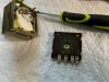
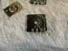
This is the Volumn Pot already taken apart. The dark board on the top has been cleaned and the board on the bottom should look just like it but has not been cleaned yet. They are very easy to clean just using a pencil eraser (the pink one seems to work best) but just spraying contact cleaner in the pot without taking it apart won't make the bottom board look like the top board. Also I carefully cleaned the little fingers on both of the white round pieces. Below is a closeup of the top board before cleaning it.
upload_2022-10-31_10-21-33.jpeg
And below is a picture of the bottom board after cleaning half of it.
upload_2022-10-31_10-23-26.jpeg
You can definitely see the difference after cleaning half of it just using a pencil eraser. I finished cleaning and reassembled the Volumn pot and put it back on the board.
 
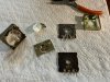
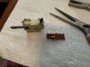
Next I tackled the toggle switches. I took each one off the board, took the bottom off of the switch (carefully bend the little metal pins straight to be able to remove the contact board) and cleaned the contacts also using a pencil eraser, reassembled it and put it back on the board. Those little copper contacts slip on and slide across the contacts on the board which are silver. Be very careful when trying to reassemble the switch, bending the pins back out is dangerous and you can easily break off one of the solder pins on the bottom of the board (yes I did that and had to locate a replacement switch on the internet, many times experience is gained the hard way). Below you can see the switch and contacts before and after cleaning.
upload_2022-10-31_10-27-33.jpeg
Before cleaning
upload_2022-10-31_10-31-31.jpeg
After cleaning one set of the contacts. I took a pencil and a razor knife and cut a slot in the eraser to use it as a cleaning tool. It might be the cheapest tool on my bench but it works quite well. I also took a burnishing tool (very fine grit metal tool partially visible on the upper right of the picture) and quickly slid it in between both copper contacts to clean them.
upload_2022-10-31_10-33-4.jpeg
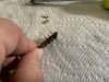
It's hard to get a good picture once the contacts are cleaned because they reflect the surroundings, but you can see the contacts on top are cleaned and the row of contacts on the bottom have not been cleaned yet. I finished cleaning this switch, reassembled it and replaced it on the board. I worked my way thru each toggle switch and both of the turnover switches which also contain the same silver contacts (the mechanical part can be left alone).
 
There are three switches I have not been able to get apart to clean; the balance control and both the treble and base controls. I damaged the bass control (and am waiting on a replacement from the internet) trying to get it apart so I won't touch the three of them unless anyone else can explain how to properly get them apart and back together again?

Also the push button switches on the three upper boards (Speaker Selector Board, Filter Board, and Function Selection Board) can be cleaned by spraying cleaner into them from the front and working them many times as everyone here has done before without having to take them off the boards.
 
Since getting the unit in it's current position is very hard (not to mention intimidating and I'm not completely sure I will get it back together properly as this is the first radio this complicated I have gotten in this position) I want to replace anything that needs replacing so I don't have to do this again (at least hopefully not) on this unit. I have already replaced most all of the capacitors on all boards (tone, flat amp, speaker, filter, and function selection) except the little Blue Dot ones (I'm not that familiar with them). If I remember correctly there are only two sizes on these boards; 35v .10uf, and 25v 1.0uf. Are they film caps? Would I replace them with WIMA film caps? The blue dots seem to be polar as the plus side is indicated on the cap and the board. I thought WIMA caps were non-polar so I'm not sure what to replace them with, but I have seen that they should be replaced on any vintage equipment and I don't want to risk not replacing them.

Also there are two transistors (2sa726) on the flat amp board that I need to replace as they tend to be problematic. I haven't ordered the replacements yet (Ksa992 I believe) as I need to get the replacements for the blue dot caps at the same time.

While working along I have already replaced the main light bulb that did not work and the phono indicator bulb that did not work. Both are working fine now.

So this is where I am now. Once I get this part completed (my replacement bass switch installed, both transistors replaced, and the blue dot caps replaced) I'll start trying to put the front of the unit back together and test my progress so far.

I'll post again as soon as I have some more progress.
 
Yes you are correct, they cost me about $25.00 apiece
that's ridiculous. mine was $16 and i wasn't happy about that.. $100 for 4 is just greedy people taking advantage. i couldn't do that. i wouldn't feel right about charging prices like that even if it is the "going rate"
 
Well I figured out that most of them boards will come out from the bottom without taking the whole front off of the radio, so I put most of the front back together tonight. I'm still waiting on a few parts (transistors to replace the 2sa726's, and my bass pot, for ex.) to come in so I can't completely reassemble it just yet.

Unfortunately this has not been a journey without peril, I put every set of screws in separate cubbies in a container as I took everything apart and then, while getting everything ready to work tonight I bumped the container knocking all of the screws onto the floor. However I had put some screws back into the holes they came out of so it was not as bad as I at first thought. I had a bunch of pictures of the front in various stages of breakdown so they went back together easier than I thought.

The really nerve racking part was trying to get the Dial String back in place and working properly, never messed with one of those before. That was very tedious but I think I got it done and the way to adjust this one is to just slide the pointer across the string as it is not glued in one place. So when I get the radio back working I should just be able to tune into a local station, get the signal strength and tuning meters maxed and then be able to move the pointer to its proper location, at least I hope it goes that well. I know, best laid plans of mice and men....

Now if I didn't break any wires from any of the boards, miss anything, or just generally screw something up, hopefully it will all work properly. Unfortunately I can't test anything as the replacement bass pot I had to order hasn't come in yet so I'll have to wait for any testing...

I'll post a few pictures a little later as that process (I take pictures on an iPad, have to get them into the proper jpeg format, move them to my windows desktop, and then upload them) takes a little time and I need a break for a little while....

 
I bumped the container knocking all of the screws onto the floor.

it happens. i knocked a drawer with about 40 film caps on the floor the other day. well, some made it to the floor, and some in a drawer and some in another drawer and a couple in the garbage can. i can get pretty creative with profane phrases sometimes.
 
Back
Top Bottom