• The move to the new server is done. There are some software and database maintenance updates in process. This has us passing the hat around to help out. We appreciate any donations. Seriously, even a dollar helps. The payment page may be found here - https://www.audiokarma.org/support.html

SX737 Issue - no sound

YoSeth

New Member
I posted last week regarding replacing the 725 and 1313 transistors in the phono preamp of my 737. I decided to dive in and took care of the 6 transistors on the phono board, and everything went well. Tested it and it was great!
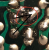
Feeling confident since the phono board went so well, the next day I opened it back up and decided to replace all of the 725/726’s on the tuner assembly, control amp, and power amp. The only small hiccup was when I pulled a 726 on the control board, a small portion of the board’s green coating came off with it.
I hooked everything back up to test, and I got an FM signal for a few seconds. I the flipped the filter levers and the sound completely cut out. Now there is no sound at all. The relay doesn’t even click after I flip the power switch.
Any ideas what could be the issue?
 
Register to hide this ad
First guess: transistor installed wrong, check every one you replaced, start with the power amp.
If you do find one installed incorrectly replace it, don't reuse it.
If you don't find one wrong it will take troubleshooting to find the reason.
 
Can you post a photo of this? Did the pad lift off?
yXz4hnJ.jpg
 
go over your work and clean up the solder splatter ... thinking about it i am wondering why it splattered like that .
then repair the trace .
I’m curious why it did that too. This was the only spot that I had that issue. I’ll clean it up
 
FWIW, I went back and double checked all the transistors I replaced; they are all oriented correctly. I suppose the pad coming off the control amp circuit is the problem. Never repaired a trace before but I’ll research it thoroughly!
 
So I cleaned up the suspect area on the control amp board. I scraped down to the fresh copper next to where the pad had lifted off, installed a new transistor, and soldered it to the copper trace. I was hopeful that this would be the fix but I still have no sound..
 
Do you have a DMM? Is there continuity between these three solder joints?
 

Attachments

  • Screen Shot 2020-09-16 at 12.41.32 AM.png
    Screen Shot 2020-09-16 at 12.41.32 AM.png
    150.1 KB · Views: 11
Decided to check the DC offset at the control amp assembly board.

Right Channel is 7.1v :(
Left Channel is 0.4mv
 
Decided to check the DC offset at the control amp assembly board.

Right Channel is 7.1v :(
Left Channel is 0.4mv
Where are you measuring this voltage? The Control Amp pcb stages are ac coupled . . .
The term 'dc offset' usually refers to a condition at the output of the power amp stage, that indicates a defect, if it is out of tolerance. It also refers, in general terms to an ac signal that has a dc component, but that is not necessarily a failure.
 
Where are you measuring this voltage? The Control Amp pcb stages are ac coupled . . .
The term 'dc offset' usually refers to a condition at the output of the power amp stage, that indicates a defect, if it is out of tolerance. It also refers, in general terms to an ac signal that has a dc component, but that is not necessarily a failure.
Measuring where the left and right comes out of the control amp assembly and goes into the power amp assembly
 
OK, there should not be a dc voltage there, check to see if C24 is backwards or leaky. Does the dc go away if the High Pass filter switch is turned on?
 
Back
Top Bottom