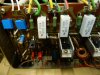
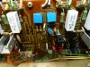
I appreciate everyone’s input on this forum and I have learned a lot from reading about other people’s issues. I was inspired to take on my first project, of this type, knowing there was a lot of knowledgeable people on the forum. I am restoring an SX950 that I bought new in 1977. It worked when last turned on - 5+ years ago and the only thing that wasn’t original is a fuse that was replaced in 1978. As I have read about others working on SX-x50 series receivers, the initial inspection of my unit indicated that I was, likely, starting with a unit that was in better shape than most. I hadn’t used it much since purchasing an AV receiver 20 years ago. No bulging caps, no evidence of smoke or anything else. And the exterior is mint.
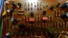
In the last couple of weeks I replaced all the caps and transistors in the power board, the protection board, the phono board, the flat amp and tone boards. I also replaced all the diodes, including the two zeners, on the power board as well as the main (22,000mF) filter caps. I deoxited the pots and switches and replaced the power cord. WIMA film caps went in for the 2.2mF and smaller caps. Nichicon PWs in the power lines and KT and KL’s in the signal path. All are rated at the same or higher voltage and/or temperature when compared to the oem caps. I purchased most of these components, in kits from Peace.Love.and.Music, from Milwaukee, and he included good instructions. After all that, the 100w bulb dimmed, but the unit didn’t come out of protection. I plugged the unit in directly and was very happy when the protection relay clicked. Now on to the power amp.
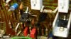
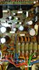
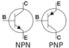
I replaced the twelve transistors, the eight electrolytics, and the four trimpots (multi-turns). KSA992s for the A726, KSA1381 for the A818, KSC3503 for the C1628, KSC2073 for the D381 and KSA940 for the B536. The 992’s went on the board backwards compared to the original 726s and the rest of the transistors went in the same way the old ones came out. The only issue that I had working on the amp board was that the legs of the KSC3503 were too wide to fit through the board so I used a 1mm hand drill to ream out the holes. No visible damage to the pads or traces.
At that point, I shudda tried it on the dim bulb - when I finished the board, but, I wanted to test the output transistors. I mucked up the first mica trying to remove it and although the other 7 are intact, I replaced all 8 of them with pink Keratherm insulators (https://www.amazon.com/gp/product/B08HZF342L/ref=ppx_yo_dt_b_asin_title_o08_s00?ie=UTF8&psc=1). Using my brand new $15 component tester, the gain was 77, 55, 45, 70 for the 2SB557-R, and 39, 42, 47, 32 for the 2SD427. I remounted the board and heatsink, and installed (carefully) the thermo-diodes (a great bit of advice from this forum).
But, the bulb didn’t dim this time and the lights in the unit didn’t light up at all. I pulled and verified that all the fuses are good. So I am seeking guidance on where to start. Am I wrong to think the problem is likely in the power amp? Could the Keratherm insulators be causing a short? Should I order replacement output transistors - given the range of differences in gain?
In the last couple of weeks I replaced all the caps and transistors in the power board, the protection board, the phono board, the flat amp and tone boards. I also replaced all the diodes, including the two zeners, on the power board as well as the main (22,000mF) filter caps. I deoxited the pots and switches and replaced the power cord. WIMA film caps went in for the 2.2mF and smaller caps. Nichicon PWs in the power lines and KT and KL’s in the signal path. All are rated at the same or higher voltage and/or temperature when compared to the oem caps. I purchased most of these components, in kits from Peace.Love.and.Music, from Milwaukee, and he included good instructions. After all that, the 100w bulb dimmed, but the unit didn’t come out of protection. I plugged the unit in directly and was very happy when the protection relay clicked. Now on to the power amp.
I replaced the twelve transistors, the eight electrolytics, and the four trimpots (multi-turns). KSA992s for the A726, KSA1381 for the A818, KSC3503 for the C1628, KSC2073 for the D381 and KSA940 for the B536. The 992’s went on the board backwards compared to the original 726s and the rest of the transistors went in the same way the old ones came out. The only issue that I had working on the amp board was that the legs of the KSC3503 were too wide to fit through the board so I used a 1mm hand drill to ream out the holes. No visible damage to the pads or traces.
At that point, I shudda tried it on the dim bulb - when I finished the board, but, I wanted to test the output transistors. I mucked up the first mica trying to remove it and although the other 7 are intact, I replaced all 8 of them with pink Keratherm insulators (https://www.amazon.com/gp/product/B08HZF342L/ref=ppx_yo_dt_b_asin_title_o08_s00?ie=UTF8&psc=1). Using my brand new $15 component tester, the gain was 77, 55, 45, 70 for the 2SB557-R, and 39, 42, 47, 32 for the 2SD427. I remounted the board and heatsink, and installed (carefully) the thermo-diodes (a great bit of advice from this forum).
But, the bulb didn’t dim this time and the lights in the unit didn’t light up at all. I pulled and verified that all the fuses are good. So I am seeking guidance on where to start. Am I wrong to think the problem is likely in the power amp? Could the Keratherm insulators be causing a short? Should I order replacement output transistors - given the range of differences in gain?