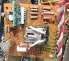
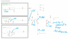
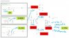
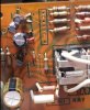
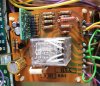
An SX980 that I’m restoring has a problem with the protection board where the relay does not energize. I believe the problem is with the PA3004 IC so went ahead and replaced the it with the ‘substitute PCB’ designed by merlynski and alexhastings (see PA3004 chip PCB substitute). A big thanks to Alex for sending a populated board for me to try! The good news is that the protection relay now engages when the unit is powered up. Unfortunately, it engages almost immediately. There is no time delay. Below are the voltage readings I was getting initially with the defective PA3004 chip, and after replacement with the PA3004 substitute PCB:
Pin# Expected Initial with PA3004
Substitute
pin 1 +13V +12.3V +12.3
pin 2 N/C
pin 3 +0.7V -0.26V +0.79V
pin 4 ~0V ~0V +0.004V
pin 5 GND (0V) 0V 0V
pin 6 -7V -0.95V -13.5V
pin 7 0.75VAC 0.72VAC 0.53VAC
pin 8 +7.2V -0.29V +0.013V
Initially Pins 3, 6, and 8 were all way off the expected voltages which is why I believed the PA3004 was faulty. With the PA3004 substitute PCB in place pin 3 is now OK as it can feed the base of Q2 and engage the relay coil. The voltage on Pin 6 is high compared to the expected -7V (taken from the service manual schematic), but Alex suggested in his description that -7V to -13V is OK. Pin 8 continues to be off, although now different. Finally, the AC on Pin 7 dropped by 200mV with the PA3004 substitute PCB installed.
A few other comments:
- I am not the first one to work on this unit as some components appear to have been replaced.
- Q2 identified in the SM as 2SC1438 had been replaced with a ECG194. I had planned on replacing this with KSC2383 but tested the ECG194 and confirmed it was functional NPN with gain ~ 120.
- As you can see from the photos the relay cover is missing. The solder looks untouched so I’m assuming this was the original but I do plan to replace it.
- I’ve replaced all capacitors
- I checked the voltages on binding posts 1-10 of the AWM-124 protection board and all appear to be as expected.
I inspected the PA3004 substitute PCB when I received it and found that one of the SMD resistors had fallen off in transit so replaced it, but it’s possible there’s other damage that I didn’t catch. I’ll keep scratching my head but am open to any troubleshooting suggestions.
Pin# Expected Initial with PA3004
Substitute
pin 1 +13V +12.3V +12.3
pin 2 N/C
pin 3 +0.7V -0.26V +0.79V
pin 4 ~0V ~0V +0.004V
pin 5 GND (0V) 0V 0V
pin 6 -7V -0.95V -13.5V
pin 7 0.75VAC 0.72VAC 0.53VAC
pin 8 +7.2V -0.29V +0.013V
Initially Pins 3, 6, and 8 were all way off the expected voltages which is why I believed the PA3004 was faulty. With the PA3004 substitute PCB in place pin 3 is now OK as it can feed the base of Q2 and engage the relay coil. The voltage on Pin 6 is high compared to the expected -7V (taken from the service manual schematic), but Alex suggested in his description that -7V to -13V is OK. Pin 8 continues to be off, although now different. Finally, the AC on Pin 7 dropped by 200mV with the PA3004 substitute PCB installed.
A few other comments:
- I am not the first one to work on this unit as some components appear to have been replaced.
- Q2 identified in the SM as 2SC1438 had been replaced with a ECG194. I had planned on replacing this with KSC2383 but tested the ECG194 and confirmed it was functional NPN with gain ~ 120.
- As you can see from the photos the relay cover is missing. The solder looks untouched so I’m assuming this was the original but I do plan to replace it.
- I’ve replaced all capacitors
- I checked the voltages on binding posts 1-10 of the AWM-124 protection board and all appear to be as expected.
I inspected the PA3004 substitute PCB when I received it and found that one of the SMD resistors had fallen off in transit so replaced it, but it’s possible there’s other damage that I didn’t catch. I’ll keep scratching my head but am open to any troubleshooting suggestions.