• Please note that Audiokarma will be offline briefly for updates early on Monday morning, September 28th.

TA7317 delay at poweron?

PE9ZZ

Event Horizon
Subscriber
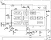
I'm struggling to get my beloved Philips DFA888 working right. The manual is inconsistent with the actual circuit around this protection IC. My problem is that it switches on its output relays way too soon, less than a second. I can only find an incomplete and very confusing (Jinglish) datasheet (attached). Now from its the internals I can pretty much figure it out but I cannot understand how the muting at poweron is performed. Is the capacitor at pin#8 slowly charging and when full triggering the schmitt trigger or is the cap between pin#6 and 7 intended for this purpose? My DFA888 is getting muted by the micro at poweroff but not poweron. The C at pin#8 would be consistent with the quick activation of the relay because it is only 1 µF (22 µF in the datasheet).

Right now it's so fast that it will go into protect because of the DC at the output. I will do some more measurements but if someone could chime in much obliged!
 

Attachments

Register to hide this ad
Found that there is a line from the micro to the TA7317. The poweron delay is actually performed by it but switching the amp off and on again quickly apparently upsets the micro so it shortens the poweron delay. The capacitor at pin #8 charges quickly so the built-in delay feature of the chip (if that is what it is) is not used. I will replace this cap and see if that fixes the issue.

Edit: Whaddya know! It solved the issue! Now there is a nice delay allowing the amp's DC level to settle before the relay energizes. Proves once again digital electronics can't be trusted because there are always bugs. No idea what has triggered this issue but it is solved now just by using the chip the way its designers intended.
 
Last edited:
No, that's the thing. The 1 µF C (CN02) is supposed to be that value:

philips_dfa888_pa_crop.jpg

The datasheet prescribes otherwise. Following its suggestion the problem is solved. Just exactly why I have no clue because it's the micro that's acting up. That signal enters at J801.

Oh, and the circuit around CN03 is totally wrong. Actually, for that they did follow the datasheet of the TA7317P. But exactly what it's supposed to do is not clear. It provides some delay to prevent relay clatter or something.
 
Well... if 22uf works and no oscillations perhaps an eng change after this unit left the factory?
I do understand the the caps purpose in general use to prevent glitches etc where it comes to various IC's where Rf and frequency and voltage can affect same. https://sound-au.com/articles/capacitors.htm#s14 explains it as it's too long..
Believe the cap would see an immediate voltage to a point of % saturation when excited so the value of uf would matter but maybe get away with 10uf?
Then wonder how much that cap saw before the clinical repair? :D
Paging @ConradH (to get his jist on subject).
 
Could the processor upset be because of the power on delay cap for the processor is not discharged (yet) when applying power a second time and the processor starts right away/too soon or even at random where it thinks it is in its program?

Talking about the processor not-rst pin 34 on the processor in the Philips schematic.
 
Could the processor upset be because of the power on delay cap for the processor is not discharged (yet) when applying power a second time and the processor starts right away/too soon or even at random where it thinks it is in its program?
Could very well be. Could even be the weird brown-out detector around QU08/9 and CU07 (point G). But I've decided to let it go. It now works as intended. Troubleshooting micro issues with a clear understanding of what the internal code is supposed to do is hard enough, without it almost undoable and not worth the effort.

Believe the cap would see an immediate voltage to a point of % saturation when excited
The purpose of this C is to slow the rise of the input voltage of the Schmitt trigger. Its input is grounded in case of a fault condition. In case there is none, like at poweron, it should rise slowly to create a time delay before the Schmitt trigger flips and switches on the output darlington at pin#6. In the Philips apparently the micro is supposed to create a fault condition by floating pin#3 during poweron blocking the Schmitt-trigger. There is activity on that output but I can't make heads or tails from it. Changing CN03 from 1.0 µF to 22 µF solves this issue with the functionality of the micro, whatever it is, intact.
 
The purpose of this C is to slow the rise of the input voltage of the Schmitt trigger.
Understand that from the capacitor function (characteristic) 1uf vrs 20uf would limit the rise longer.
Q? is the cap on all the time or just momentary?
---------
I did ask how long did the 1uf work before this fix?
---
Fun stuff... if it weren't for science I'd be bored stiff :D
 
I did ask how long did the 1uf work before this fix?
Since day one (1987) the poweron performance of this amp was lacking. First the time was too long, then it was too short. Now it is OK. With the low value it worked as Philips intended. Now it works as the designers of the TA7317P chip intended. Or at least as much as I could figure it out from the datasheet. Why it changed in the past 33 years? Your guess is as good as mine.
 
Back
Top Bottom