• The move to the new server is done. There are some software and database maintenance updates in process. This has us passing the hat around to help out. We appreciate any donations. Seriously, even a dollar helps. The payment page may be found here - https://www.audiokarma.org/support.html

Tandberg TR 2060 salvagable or not

AngelAT

Well-Known Member
Hello fellow AKs,

I got a Tandberg TR 2060 in terrible condition- without housing, some parts missing, etc. As I know how good these receivers are, I am trying my best to save it. I have and old TR 2025 that am using as parts donor for lamps' board, top, bottom and sides, etc.

The power amp of the TR 2060 was missing some components - transistors, resistors, etc. The output transistors were 4 different types and also shorted. So I recapped the power board, replaced the output resistors with new 0.68 Ohm/5w wire wounds, some other resistors, the drivers with MJEs, the dif. pairs and basically all transistors at the board, except Q703 and Q704 because they tested OK (and I do not have modern equivalent to use).
While waiting for the outputs to arrive, I recapped the rest of the unit.

My problem is that I have strange voltages at the rectifier CR775 -> +73 VDC, -7 VDC (with DBT). I also do not get the +40VDC at 12v bulb - I get 35V. Otherwise the 25VDC from the power supply is present. At the filter caps (checked OK) I get -73VDC;-33VDC and 7Vdc;-33VDC. When I check the trafo I get 29.8 VAC at pins 22 and 23 with respect to ground and between pins 26 and 28 I get 63 VAC. These make me think/hope the trafo is OK. Replaced the rectifier CR775 even though it measured ok. Also checked the four caps around it - they are also OK.

Do you have Ideas what might be causing these anomalies?
 
Register to hide this ad
If you are not sure about the workings of the power supply, just disconnect it. Like all of it. Then check the output voltages. In case the connection from PS to whatever part does not run thru a wire but only over the PCB, you might have to lift the leg of the first component after the PS. Of course you would have to make sure you got all connections covered, before you power up.
 
Ignore the +25V rail, that's got its own windings and rectification/regulation.

Since you have good AC on the PS secondaries, the question is why so unbalanced off the rectifier? As mentioned above, remove the load on the PS rails which is easiest done by just removing the output drivers, or remove at least their rail connection wires from the collectors - ok to leave the bases and emitters connected. I think I'd also look to see if something has broken or interrupted the 0 volt/ground path in the PA board.The largest components that can impact that zero point are the rectifier and caps, so that's still where I'm looking first.

What is the DBT doing as things are now? Any indication of a short? I can see that impacting the (-) rail but seems unlikely to have also boosted the (+) rail that much over spec.

Also, do you know if the PS rails were that far out of balance prior to the wholesale replacement of parts?

John
 
open rectifier and/or bad caps is most likely why the supply is so uneven. Unhook everything that isn't the rectifier and the first caps and figure out whats going on. If the supply is wrong, nothing else is going to work. This should be a full wave rectifier supply, grounded center tap, and the bridge is just a convenient way to get a + and - rail. Make sure the center tap is grounded and the caps tie to it properly. One has - to ground, the other is + to ground.

I did a 2060 maybe a year ago, was a real pain in the neck. Something had been spilled in there and some of the legs on the parts disintegrated, which took out one channel. Ended up going fairly scorched earth and pulling and testing or replacing basically everything there. Worked when I was done but it wasn't fun. One of the various problems I had was the plug for the power supply to the output transistor collectors had corroded and lost either the + or - rail. I forget which, but it came up with one supply and not the other, which kept it from coming out of protection. The connector was too rotted to fix so I ended up removing the connector and soldering the wire direct to the board.
 
Yeh.. that sounds bad Gadget. I got a 2025 here with a power amp blown on one side. It got rail voltige, I replaced the outputs (twice, also in the BCB + twisted) and the drivers (NOS), and a burned power resistor, and some caps.. I bought it as a defect from an actual repair shop where they where DONE with it.. I shelved it for now, and I'm considering to just plop one of those cheap power amp modules in it. Sjies these machines are itchy to work on! They look nice though, and from what I gather they sound good as well.
 
it was mostly annoying because it showed up working, but with some totally unrelated issue. I blew the dust out of it and some component leads vaporized without me realizing it. That took out the channel. I replaced a number of things but missed something, and it took out most of the same parts again. At that point I was annoyed and decided I was going to be absolutely sure every single component in that channel was good before it got powered up again. Thats when the power connection issue turned up, but at least that didn't cause any damage.

I worked on a 2080 around the same time. That was a nice piece, and honestly less difficult to work on than the 2060 was. Sounds awesome too.
 
Thanks guys for stepping in!

I was away for some time, but now back and will tackle this beauty.

This is not my first Tandberg - I have worked on 4-5 tr 20xx others but these were not causing me much problems - all fixed. Including my first 2060 which was also a pita to fix, but at the end all ended well.
And yes, they have a great sound!

About the current patient - I did not know how it was before, because it really came in parts. With missing components, etc.
I do not get a short on the DBT, but the outputs measured short in circuit, and OK once out of circuit.
Double checked all the new transistors legs as most are new equivalents. Replaced all small transistors with new ones - all from Mouser.

I will now focus on the power supply, as you suggest. I struggle to find a hires schematic and this is not helping me.
Will come back with updates as I proceed.
 
pretty sure the one I worked from came from hifiengine, its not super high res but it was good enough.
 
Drop me a PM with your email, I can send you a way more legible scan of the circuit diagrams document.

These receivers are mother's milk for me, I find them both easy and enjoyable to work on. Not a single twisted wire connection anywhere on the boards, and mostly modular so they come apart and go back together easily. I think you just have to do a few more to get to the point where it starts to come easier.

John
 
A quick update:

Managed to get the right voltages. As you guys suggested, it was the grounding. When I removed the PA board to rework it and then put it back, I did not put back all the screws. And these were providing the ground.

Then I could not get the relay to click again and the voltages were not right. As a result C 708 was blowing open. Came out I have messed the legs of Q702. Fixed this and now I have the click.

Fixed the 25V at the power supply.

BUT, I still cannot fix the 17mV at the emitter resistors. There I have 0.00 mV?! And this does not change with R723/724. Resistors are new 0.68 Ohm/5W wwounds. Do you have any clues why this might be?
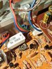
IMG_20221023_163036.jpgIMG_20221023_161135.jpg
 
sounds like no bias voltage is being fed to the base, so the output transistors are not turned on. Check the small transistor clamped to the heat sink, thats part of the bias thermal tracking circuit. Off the top of my head I don't remember what else is involved there.
 
Thanks, gadget73!
This seems not very probable, because I replaced these with new ones.
But, still, I will double check them.
 
In mine that transistor had exploded (I think) in the bad channel. It was missing about one-third of it's body. Almost forgot about that..

So yeh, there might be an issue with those, perhaps across models.
 
Thanks, gadget73!
This seems not very probable, because I replaced these with new ones.
But, still, I will double check them.

make sure its the right one too. What I found in the unit I had did not match the schematic and the pinout was not the same. I used whatever the schematic called for and re-pinned the connector cable to make it work.
 
make sure its the right one too. What I found in the unit I had did not match the schematic and the pinout was not the same. I used whatever the schematic called for and re-pinned the connector cable to make it work.
Makes sense!
Will double check and come back.
Cheers!
 
Ok, managed to fix it!!!
All is now set. I am super happy
IMG_20221023_212935.jpg

Works and sounds great!

I will now do some wood repair and painting.
Guys, I will need the aluminium frame line with the name and model number. Is there a chance that anyone of you has one?
Thanks!!!
 
great! So, was it the transistor on the heatsink?
Thanks!
Actually it was the pots -they were a bit dirty and when I wiggled left and right, all was OK. I double checked the transistors and they were all new and OK - BC548B.
Do you, by chance, have a spare aluminium frame line with the name and model number?
 
Heh, never overlook the possibility that it's actually something quite simple:biggrin:. Unfortunately I have no frames laying around to help you with.
 
Back
Top Bottom