david winter
Classical music lover.
Hi,
I'm stuck trying to find out why the capstan motor on a Teac A-3440 doesn't spin when the safety lever is pulled (as if a tape was loaded).
I restored the power supply board (recaped, all silicon diodes replaced). All fuses are good.
Capstan motor has 30V going to it. A quick test by applying a constant voltage makes it spin, so I'm quite sure it's ok. Belt is new.
I also recaped the servo pcb. Only C3 and C10 (tantalum) are left. I doubt they are done.
I tested all resistors around Q2 and Q3: all test exact.
At pin 13 (output) of the dual op-amp I have 20.2V.
I also have 10V and the emitter of Q2, but 0V at the collector which is the problem.
All transistors tested fine on my Peak tester (unless I missed someting).
I made a quick test by disconecting the collector and emitter of Q3 to see whether I would get some voltage at the collector of Q2 but no luck.
All resistors around Q2 and Q3 test perfectly.
When I power up the deck and pull the safety lever, the capstan wheel makes a quick 1/4 turn and stops.
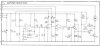
Note that on the schematic below, either R8 or R9 go to R10 depending on the tape speed. Eventually another trimmer is connected between when enabling the pitch control.
Finally, I don't think the dual op-amp (NJM2901N) is bad. At least the voltage at the output would allow the motor to spin even at incorrect speed.
Any ideas ?
I'm stuck trying to find out why the capstan motor on a Teac A-3440 doesn't spin when the safety lever is pulled (as if a tape was loaded).
I restored the power supply board (recaped, all silicon diodes replaced). All fuses are good.
Capstan motor has 30V going to it. A quick test by applying a constant voltage makes it spin, so I'm quite sure it's ok. Belt is new.
I also recaped the servo pcb. Only C3 and C10 (tantalum) are left. I doubt they are done.
I tested all resistors around Q2 and Q3: all test exact.
At pin 13 (output) of the dual op-amp I have 20.2V.
I also have 10V and the emitter of Q2, but 0V at the collector which is the problem.
All transistors tested fine on my Peak tester (unless I missed someting).
I made a quick test by disconecting the collector and emitter of Q3 to see whether I would get some voltage at the collector of Q2 but no luck.
All resistors around Q2 and Q3 test perfectly.
When I power up the deck and pull the safety lever, the capstan wheel makes a quick 1/4 turn and stops.
Note that on the schematic below, either R8 or R9 go to R10 depending on the tape speed. Eventually another trimmer is connected between when enabling the pitch control.
Finally, I don't think the dual op-amp (NJM2901N) is bad. At least the voltage at the output would allow the motor to spin even at incorrect speed.
Any ideas ?