• The move to the new server is done. There are some software and database maintenance updates in process. This has us passing the hat around to help out. We appreciate any donations. Seriously, even a dollar helps. The payment page may be found here - https://www.audiokarma.org/support.html

TEAC A2300SD not recording

Pioneerhead

New Member
Hello, I am new to the forum and need some hopefully expert input.
I recently acquired a TEAC A2300SD in very decent condition. I re-lubed all the standard areas discussed on Youtube. I also deoxed all switches and pots. Everything works as it should with the exception of the record mode. It does not record. The heads look very clean.
Both record toggle switches are in ON mode. Bias set to 1. Monitor is set to Source. Use brand new tape. Record light is red. Started recording with phone as source. Set Line Level accordingly. Have audio on both channels and VU needles move accordingly. When I switched Monitor from Source to Tape, I hear nothing. No needle movements. The unit will play back other recorded tapes.
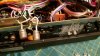
The only thing I can think of is the unit came with the Line-In jack support broken and the jacks were just hanging loose. I purchased a new jack from TEAC and replaced the old one. The new jacks come with support built-in. I was very careful to only unsolder and resolder one connection at a time so as not to mistakenly put connections incorrectly. The solder joints are solid with no loose solder joints.20171028_004126.jpg 20171031_111459.jpg 20171024_211606.jpg 20171030_215028.jpg
Thanks for any input.
 
Register to hide this ad
Greetings from RojoLand!

Congrats on your "new" acquisition!

Since you're seeing the red Record light, the Record relay (K401) is firing — but it's likely that not all its contacts are making connection. It's a four-pole, double-throw relay. One of the contact sets applies power to the bias oscillator, and if that's not getting power you won't have record. Also check L21, a 2.2 mH choke which if open will prevent power from getting to the oscillator as well. Collectors of Q20 and Q21 should have around 20 V on them (measured to chassis ground) when in Record mode.

If you don't already have it, the service manual can be downloaded at HiFi Engine. https://www.hifiengine.com/manual_library/teac/a-2300sd.shtml

Good luck!

Take care,

J. E. Knox "The Victor Freak"
 
Thank you for your response. I have downloaded the service manual (hifi engine is great); however, I am not an electrical engineer (:. I did manage to find the K401 relay on the schematic and that it's located on the Control PC board. It looks pretty involved to remove the board to check the relay. Assuming I can remove the board, can i physically see if not all contact sets are making contacts? or do I have to take some measurements with a meter? Also, if it's bad, can you just replace the relay or do you have to buy a whole new board? Much thanks.
 
Greetings from RojoLand!

Relay K401 is actually located on the Bias Oscillator board. (See page 35 of the service manual.) It will be fairly hard to determine the contacts' condition visually (especially if you have bad eyes like me!). An ohmmeter test is best, but you would have to power the relay externally (with deck power off) to test the normally-open contacts. One could replace the relay assuming a proper replacement can be found. It would have to match the contact pattern to properly fit on the PC board. If you can get the plastic cover off the relay, a shot of DeoxIT D5 might be all it needs. Before going to that trouble, though, check the contacts that apply 20 VDC to the osc circuit. That's the leftmost of the four switch contacts as seen on page 35, about a third of the way down on the right side of the board. L21 is above and to left of K401, just right of oscillator transformer T20. Look for about 20 VDC on either terminal of L21 (in Record mode). If you find no DC on either terminal, check the leftmost normally-open contact on K401. (Note that the normally-closed contact has no connection.) If there is DC there, check the wiper contact (just below the NO contact). If DC is present there (again, in Record mode), and you had no DC on L21, then the trace is broken (or a bad solder joint exists) between K401 and L21. If no DC is present on the NO contact, check for DC at terminal 3, top edge of the Bias Osc. board. If DC is there, the trace is broken between terminal 3 and the leftmost NO contact of K401. These boards can be found with broken traces — had it happen with my Teac A-6300 when it suddenly quit recording. In that case, a break on the control board kept the record relay from operating, so no record!

If you find that the DC is getting through and the bias oscillator is actually powering up, we'll have to dig deeper. Servicing gear like this is a matter of divide-and-conquer.

Take care,

J. E. Knox "The Victor Freak"
 
Thank you. I removed the Bias Oscillator board. The relay is a little tough to open up. Still working on that. Want to make sure I don't break the cover.
 
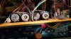
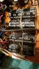
I had to remove the brake system in order to free up the wire harness so the BIAS OSC board can be more exposed20171101_215255.jpg 20171101_215645.jpg . However I noticed burn-like marks at the end of these capacitors. When the machine is on, I noticed a smell like something burned coming from this area. Are these burn marks normal or are the capacitors burned out? If so, would it be the cause of the unit not recording?
 
Greetings from RojoLand!

Hoo-boy. That's the ground end of those caps, but given that large dark area on them and the smell you're getting, I think those are prime candidates to be replaced. Can't do it right now, but I'll have a look at the schemo and see if they have any real bearing on your no-record issue.

Take care,

J. E. Knox "The Victor Freak"
 
Greetings from RojoLand!

Just looked over the A-2300SD service manual again. It appears a number of power-supply filter caps, including those four large ones, are mounted on that board. Schemo itself doesn't point that out, but the parts are right there on the board diagram and, obviously, on the actual board. Go figger. Any-hoo, you definitely should change out ALL the electrolytic caps on that board particularly (and doing the whole set wouldn't be a bad thing). The power supply schemo is on the page marked "Tape Transport." Bias osc gets its power input on pin 4 of the osc board, which comes from Control board pin 37, which comes from the Osc board pin 37 (!) [Who designed this stuff?] At least that's how the schemo reads.

Take care,

J. E. Knox "The Victor Freak"
 
Bias osc gets its power input on pin 4 of the osc board, which comes from Control board pin 37, which comes from the Osc board pin 37 (!) [Who designed this stuff?] At least that's how the schemo reads.

Pin 4 on the Bias Ocillator board shown on the Preamplifier drawing connects to pin 37 on the Control PCB shown on the Tape Transport drawing which is the output of the 24VDC power supply (the emitter of series pass transistor Q1).
 
i will definitely replaced all the caps on the Bias board. It should be interesting since I have never done this before. Did you get a chance to determine if the Bias board caps affects the not recording issue? Also, how about the Amp B board? BTW, do you have any recommendations on where to buy caps? Much thanks
 
Greetings from RojoLand!

Pin 4 on the Bias Ocillator board shown on the Preamplifier drawing connects to pin 37 on the Control PCB shown on the Tape Transport drawing which is the output of the 24VDC power supply (the emitter of series pass transistor Q1).

Correct — and Q1 (2SD288[K]) is located on the Bias Oscillator board (!). (Indeed, looking at the Control board photo I don't even see a "pin 37" — so that's confusing too. The power supply components appear to mostly be on one half of the Bias Osc board.)

The four large caps are major parts of the power supply, and they should be replaced. Not too worried about the Amplifier B board at this point. The Rec EQ and Rec Mode switches connect there. I'd still like to know if the Bias Osc itself is coming on in Record mode.

Take care,

J. E. Knox "The Victor Freak"
 
The capacitors should arrive by Tuesday next week and I will replace them. How would I be able to tell if the Bias Osc comes on during Record mode? Just out of curiousity, I bought a Bias Osc board that was on eBay.
 
Greetings from RojoLand!

I detailed some voltage checks above, in an earlier post. Follow those to determine if the bias osc is running properly.

Take care,

J. E. Knox "The Victor Freak"
 
Ok. Hopefully I will have some time to take those measurements in the next couple of days. In the meantime, the replacement capacitors i ordered came in. They have the same ratings but they are physically smaller than the original ones on the board (see pic for comparison). Did i ordered the wrong type? I have done quite a bit of soldering in my previous radio control hobby but am new with electronics. Are there current ratings for capacitors I should have been aware of?20171104_224047.jpg
 
Greetings from RojoLand!

Not to worry. Most capacitors these days are considerably smaller than those of the same capacitance and voltage ratings made 40 years ago. It's even better when you're replacing caps in decks like 1950s Webcors (I've done my three rigs) or the 1962 Concertone I just finished up. As long as you got the same capacitance and voltage values, you should be good to go. Only thing I might have suggested is to upgrade to 105°C-rated parts where possible. The old ones will most likely be 85°C. No harm in using new 85°C-rated parts though.

Take care,

J. E. Knox "The Victor Freak"
 
Back
Top Bottom