• The move to the new server is done. There are some software and database maintenance updates in process. This has us passing the hat around to help out. We appreciate any donations. Seriously, even a dollar helps. The payment page may be found here - https://www.audiokarma.org/support.html

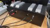
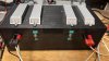
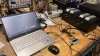
Teaser Pics -- Fisher SA-100 clone in progress

In high wattage anything other than wirewound is rare. So we look for resistor done in non-inductive winding techniques. I’m not sure if the so-called low-inductive resistors are acceptable.

I’m believe a NHS50 series resistor would be OK, but could only find it in 100W form at $11.29: https://www.mouser.com/ProductDetail/ARCOL-Ohmite/NHS100-16R-F?qs=MLItCLRbWswZnwOdqkvQBQ==

Part Express has a bifilar wound 20 watt resistor which might be right for short tests of this amp, at under $5 each: https://www.parts-express.com/Dayto...udio-Grade-Bifilar-Resistor-007-16?quantity=1
 
Span -- Regarding your questions:

1. Yes, for the reasons I cited in point #2 of my post #237.

2. The preferred way of course would be to use a Distortion Test Set, and adjust the AC Balance control for the lowest possible THD at 1 kHz, at a level of 1 db below full power output. But it's still possible to set the control with good accuracy with little more than a DVM and a scope. In that case, after the DC balance has been set, the amplifier is driven by a 60 Hz sinusoidal test signal (available from any low voltage step-down transformer) to a power output level of about 10 watt RMS. Across an 8Ω load this would be 9 vac. One channel of the scope is AC coupled to each output tube cathode terminal, and the images adjusted to reside on top of each other. The AC Balance control is adjusted to produce equal amplitude pulses at both output tube cathode terminals.

Dave
 
I checked the Heathkit AA-100 schematic to be sure I had the output wires correctly- and that checked out. What I did see is this resistor and capacitor across the ground and 16 Ohm taps. Wonder if this would improve the performance? It ties into feedback to the first section of the 7199 driver tube, so maybe not. Just thought I would throw it out there.

Screen16.png
 
Some designs will use such "Zobel" networks connected across the output of the amplifier to effectively maintain the presence of a load at supersonic frequencies at all times on it to help produce optimum load stability under speaker load conditions. This was not found necessary in the clone design, with absolute stability achieved without the need for such an expedient.

Dave
 
I am building a new dummy load that has 8 and 16 ohm abilities. What is the best way to drop the level so I can use a sound card to use a few measurement tools on a laptop? True RTA and the like. Suggestions?
Also including panel mount BNC (50 ohms) to connect to my scope using a BNC-BNC (50 ohm) cable. Kosher? Presume 1X scope setting.
A few circuits here, not simple circuit for a simple test. http://www.pmillett.com/ATEST.htm
So maybe a voltage divider would work?
All that being said, not sure what corrections I could make if I see problems with the output of my clone.
 
Last edited:
We are digressing the thread, but I would really like to know that too. There are probably other ways to do this too, but effectively I believe you need an interface like a Focusrite Scarlett Solo, or the like.

There is a thread that talks about this at length, and introduced using free REW software for amplifier distortion testing here: https://www.diyaudio.com/community/threads/how-to-distortion-measurements-with-rew.338511/ Unfortunately I find the thread long, hodge-podge and difficult to quickly glean the information I need to start; i.e. knowing what to get and how to do it. I’m not faulting the thread, I’m just wishing for a concise, simple overview and instructions of how to do it.

What we really need a sticky thread on AK titled “Simplified test suite to characterize audio amplifiers” to cover this whole area in beginner’s language. Wonder if we could entice the experts to share their amplifier testing knowledge in this manner?
 
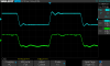
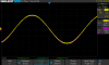
Update: Built a new dummy load box with 8 and 16 ohm options. Waveform is slightly improved (1Khz and 10Khz)- these waveforms are on an 8 Ohm load. I am working on the 16 ohm- need to break out the 16 ohm leads on the output transformers. (Have another USB "sound card" coming- Focusrite Scarlette 2i2- has better controls than what I have been using)

IMG_5418.JPG IMG_5416.JPG SDS00070.png SDS00071.png IMG_5415.JPG
 
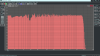
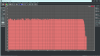
After some wrangling did a pink noise test using TrueRTA and Focusrite 2i2 sound card box. Happy with this - using the 16 Ohm Taps.
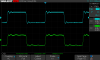
Oscilloscope screen grab is 10 Khz square wave measured at the 16 ohm tap.
Sine wave clipping is just over 19.8 Watts.
 

Attachments

  • PINK R CH Focusrite .png
    PINK R CH Focusrite .png
    247.7 KB · Views: 12
  • SDS00075.png
    SDS00075.png
    21.9 KB · Views: 13
Last edited:
The blue line is your square wave input? What is your generator? It looks like it has some overshoot, but I’m not expert on what clean square waves should look like.

Comparing to Dave451 I noticed that he had some difference between the channels. https://audiokarma.org/forums/index...sher-sa-100-clone.861966/page-2#post-12572532

What values are you using for the components Dave G discussed in his note 5 on the schematic? Obviously he also had some difference between the channels that he addressed in this manner.

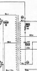
Note 5 on the bottom left of schematic says:
(Resistor)
L = 2.7k
R = 1.5k

(Capacitor)
L = 150pf
R = 180pf
 
I split the difference for those values- using 160 pF and 2.2K. Not sure I posted it, but made a test fixture with a trimmer and potentiometer to scan the various values to reduce the overshoot/ ringing on the right channel especially- the optimum values were virtually the same as what I used, so left the fixed components as is. Going back to the first time I fired up the amp the right channel always had more ringing and short of swapping the inputs to the transformers to check I am going to live with it. More testing to come as I delve more into this part of the journey.
The Pink RTA sweep was using pink noise from a sound file to an Audioquest Dragonfly RED. This site for $15 you can create sound files of all types.
https://www.wavtones.com/functiongenerator.php

I realize through all these devices there will be some cumulative errors, but when looking at the DAC output, not thru the Clone amp it is OK.
High-end lab gear? No, but serviceable.
 
"Wordless Workshop" - who remembers those? Written by Roy Doty in Popular Science magazine way back.
Anyhow- cooked up this mangy meter box to check bias in one stop- it is easier to set DC Balance and Bias.

IMG_5494.jpg

IMG_5493.jpg
 
Last edited:
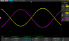
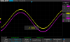
This might be helpful- check my work, but this is how I set AC balance. I have test points connected after the phase inverter before the .1 uF capacitor. I had to add the test points after I had the whole thing built, but luckily I had room. Get the two traces going and invert one and get them to overlay perfectly. I found that the balance tracks perfectly through the range of input levels.
 

Attachments

  • IMG_5500.jpg
    IMG_5500.jpg
    118.4 KB · Views: 16
  • SDS00076.png
    SDS00076.png
    24 KB · Views: 15
  • SDS00078.png
    SDS00078.png
    25.1 KB · Views: 13
  • SDS00077.png
    SDS00077.png
    20.8 KB · Views: 15
Last edited:
Doing some good work here, George. Thanks for sharing it with the rest of us.Very inspirational, but, yet, I find ways to procrastinate :(

I wonder if you have done any further tweaking of the RC values mentioned in #252. Would that not be the way to improve your 10kHz square wave on the “less pretty” channel? Or do you believe the “inbetween”values you used are still the best compromise. It is clear that Dave G had to use different values for the two channels to get his nice and equal end results.
 
Last edited:
I mentioned that I built a test rig with a potentiometer and variable cap/ trimmer and found that the values I used were as good as it gets in terms of the ringing.
I split the difference using Dave's values; 2.2K and 160 pF.
I ran some tests for frequency response using TrueRTA and then REW. On both programs I used the internal generator and then used a WAV file from a MacPro using Audioquest Red Dragonfly. The A/D converter is a Focusrite S2S V.2.
This is TrueRTA "quick sweep" internal generator result. Seems too good to be true!Quick Sweep RTA.png
 

Attachments

  • IMG_5332 2.JPG
    IMG_5332 2.JPG
    86.5 KB · Views: 10
Back
Top Bottom