• The move to the new server is done. There are some software and database maintenance updates in process. This has us passing the hat around to help out. We appreciate any donations. Seriously, even a dollar helps. The payment page may be found here - https://www.audiokarma.org/support.html

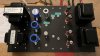
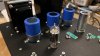
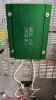
Teaser Pics -- Fisher SA-100 clone in progress

Thanks Selmerdave- I swapped the primary leads-the problem persists. Dang it. I may try disconnecting the feedback and see if that is part of the problem, but first double check the wiring of the first stage. In reading different articles- low screen voltage might cause it or driving the output tubes too hard- causing surges in the power supply which seems unlikely given the amount of filtering going on with this design.
I have found this guy to be pretty knowledgable- YouTube about motorboating-

I see you have a ROK- I have rebuilt about 3- have one someone gave me, but in rough shape... get to that after this. My nice Rondine has the Ashland motor.


I think your output transformer primary probably needs to be reversed for polarity, you're getting positive feedback rather than negative feedback.
 
Last edited:
Thanks Selmerdave- I swapped the primary leads-the problem persists. Dang it. Wonder if there is a sure way to insure that the primaries are in the right orientation even though that didn't fix my issue.
I see you have a ROK- I have rebuilt about 3- have one someone gave me, but in rough shape... get to that after this.
Sorry that didn't help, I had that problem on a previous build. Yes the ROK's are great...
 
Hi George,
Congratulations with passing the smoke test! I’m sure you will lick the motorboating soon! I would definitely disconnect the feedback to see if that helps. If it does I would guess the secondary connections (from where the feedback is taken) are in the wrong phase.

Good luck and congratulations again.
 
Thanks for the encouragement!
I swapped the primaries of the OPTs- no dice, still sings like a bird. Tried a coupling cap (.1) on the input- no dice.
I am going to work down the list of usual suspects:
-Remove the feedback loop- see what happens.
-Double-check the input stage wiring
-Back off the EL84s a bit but I kind of doubt that is it, but is mentioned in a few articles.
I already have the output grid stoppers really close to the sockets.

In the meantime, I have a noise machine. Not in a hurry- that never ends well with tube gear.


Hi George,
Congratulations with passing the smoke test! I’m sure you will lick the motorboating soon! I would definitely disconnect the feedback to see if that helps. If it does I would guess the secondary connections (from where the feedback is taken) are in the wrong phase.

Good luck and congratulations again.
 
Is the OPT secondary COM lead grounded? It needs to be if not.

The fact that it misbehaves when a source is connected tells me it is probably something to do with the first stage wiring. Since the feedback connects into the first stage, you can try to disconnect the feedback to see if you learn anything new.
 
Thank you Kward- The secondary is not currently grounded- Missed that one! Running out to my shop right now.
Still motorboating big time- and the 510 ohm 2-watt just started to smoke- cut the power.

Checked- the 510 is still OK. Disconnected the feedback - no motorboating so that is encouraging- will check the input wiring in the AM. I tried reversing the primary of the OPTs, but that was before I grounded the secondary. Guess I will try that after I check the action around the 12AX7.
Back at it in the morning. Listened to some music w/o the FB- sounds fantastic. Amazing depth and detail. Got to lick this motorboating- only sounds good on a lake.

Thanks for the tip!
 
Last edited:
Success! I did the right thing and rewired the 12AX7 socket. Moved the two NFB components to the back of the speaker terminals to make more room around the socket.
I had to swap the primaries (again) of the OPTs, but amp is sounding great.
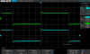
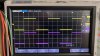
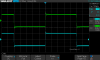
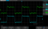
I have a few scope screen grabs attached- 1Khz at two volume levels and a 10Khz.
Things get a little dicey up the upper frequencies (SDS41.PNG).
Thinking that would involve tuning the R/Cs (Pin 6 of the 12AX7) cited in the notes?
Maybe put a trimmer in place of the fixed C and adjust until things look right and replace it with a good fixed value. Have to look into the role those play. Later.

So today will put in the time delay relay. Going forward looking to improve the upper frequency performance. I will have a look at Dave's scope screen grabs to see where I am.
Thanks for the useful tips along the way- appreciate it!
Dave is right- it does sound amazing. Thank you Dave for the V2 of the EFB circuit.

Happy Happy Mardi Gras,
George

IMG_5289.JPG
 

Attachments

  • SDS00039.png
    SDS00039.png
    18.8 KB · Views: 32
  • SDS00040.png
    SDS00040.png
    18.5 KB · Views: 31
  • SDS00041.png
    SDS00041.png
    20.9 KB · Views: 32
  • IMG_5292.JPG
    IMG_5292.JPG
    80.6 KB · Views: 31
  • IMG_5291.JPG
    IMG_5291.JPG
    75.7 KB · Views: 29
  • IMG_5288.JPG
    IMG_5288.JPG
    95.6 KB · Views: 32
Last edited:
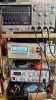
Describe your test setup a bit more. What is the blue trace depicting? What secondary tap are you measuring on? What is your dummy load?

Before going too much farther you should do a frequency response test at 1 watt output, measured from the 16 ohm tap with a 16 ohm non inductive dummy load.

But before doing that even, you should do a loop back test on your signal generator. If you have anomalies in your signal source they will come through and show up on your output. For example if your input square wave is ringing, your output will reflect that ring, if your input sine wave isn’t flat over some frequency range of measurement, your output will reflect that also. In other words this amp has the potential to become what I would call a “precision instrument” if executed appropriately, so don’t try to compensate the amp’s HF tuning for anomalies in the source signal or source equipment.
 
Last edited:
Hi Kward-
The signal gen is flat- so no introduced instrumentation errors. Using this dummy load at 8 Ohms- I didn't run a 16 ohm taps to speaker terminals anyways.
I am taking my time and won't do anything radical unless I know that it is a fruitful path. Thanks for the comments.
 

Attachments

  • IMG_5293.JPG
    IMG_5293.JPG
    92.2 KB · Views: 22
  • IMG_5295.JPG
    IMG_5295.JPG
    104.4 KB · Views: 23
  • IMG_5294.JPG
    IMG_5294.JPG
    76.5 KB · Views: 21
  • IMG_5296.jpg
    IMG_5296.jpg
    134.1 KB · Views: 22
Not sure I am doing the AC balance correctly- Readings are not
as Dave suggested-
6FQ7- Pins 1 and 6 should be 215, Pins 3 and 8 should be 100V
At the end of the adjustment range ( 5K wiper is all the way to ground)
I am at (before the .1 caps):
Pin 1/3. 234 and 76
Pins 6/8 238 and 70
Reduce the value of 20K or 22K?
 
Last edited:
I personally wouldn’t worry about those differences. The DC plate and cathode voltages on the inverter outputs could very well be different if your tubes are not matched to Dave’s reference implementation, especially with the 12AX7 being direct coupled, the DC voltage impressed on the inverter’s grid will affect the inverter’s quiescent DC voltages on its outputs.

You do however need to guarantee enough voltage swing envelope on both inverter outputs so that the inverter can deliver enough low distortion voltage swing to allow the output stage to reach full power.

AC or dynamic balance is what that pot on the inverter is supposed to be controlling. You want to adjust that pot under dynamic conditions so you have balanced outputs. Meaning adjust that pot until the AC voltage swing of the plate output matches the AC voltage swing of the cathode output.

There’s just one caveat in that adjustment though, which is you want to adjust that pot so that you have balanced signals being fed through each side of the OPT primary, and that may necessitate slightly imbalanced signals coming out of the inverter outputs themselves.
 
Thank you Kward- that helps- got it with a sine wave to balance out.
So-
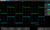
Getting close- using the 680pF and 680 ohm FB- have a problem with one channel, green one (SDS-41)- @ 10Khz. Attached the 1Khz trace as well.
From Dave's discussion- so I need to get to the bottom of this-
Pertains to the green trace:
"Were there numerous wiggles and bumps, it indicates that the design is only marginally stable, with peaks and valleys in it's response curve."
Pertains to the Blue trace:
"The nearly vertical rise followed by the small hump at the top of the wave is typical of high quality vacuum tube NFB amplifiers, indicating a well extended HF response beyond the traditional audio spectrum, necessary for the application of stable NFB."

So something upstream from the 680 pF and 680 ohm is questionable. I'll go back and check the component values. I measured each one before installing them-
More digging.
SDS00041.png SDS00040.png
 
Last edited:
Well, I spent hours trying to get the Right channel to behave at 10 Khz- green trace.
The problem originates at the output of the 12AX7.
I switched all the components on R CH associated with the 12AX7 (pins 6,7 and 8), changed out the R/C from the 4-ohm tap, and changed out all the tubes.
I am stuck.

SDS00041.png
 
Last edited:
You need to determine if the problem is a wiring error, bad wiring layout, or a bad/out of spec component. You’ve already swapped tubes and some components (so I understand) so it is probably not the tubes themselves or the components (resistors, capacitors, etc). The layout of the wiring on the right channel might be causing this if there is some sort of interaction between channels or components. Try testing the right channel by itself to help eliminate possible interaction with left channel. I'd probably remove all of the left channel tubes for that test (6FQ7 and EL84s).

If wiring looks fine but still misbehaving then I might start to suspect the output transformer itself or something associated directly with the output transformer wiring. The output of the 12AX7 has feedback summed into it already, so by the time you are seeing the 12AX7 output, it is already trying to correct for the behavior of everything else in the right channel circuit chain, including the behavior of the first stage, the inverter, the output stage, and output transformer. Not sure how hard this would be to test, since it would require swapping the plate leads and feedback connection left for right channel, but it would be interesting to see these results if you were to swap left for right output transformer. Leave them bolted in to their current locations but swap the primary leads and feedback left for right channel.

For what it’s worth, I have been bitten by this more times than I can count. I had similar behavior with one channel of my amp using these same Heathkit AA-100 OPTs. I did not build the SA-100 clone, but I did use the same OPTs in a 6V6 build. One channel looked like your blue trace (good), and the other channel sort of looked like you green trace (bad). Try as I might I could not make the bad channel look as good as the good channel. I performed the left/right OPT wiring swap and the problem moved to the other channel and then it dawned on me it was the OPT itself. See this post: https://audiokarma.org/forums/index...r-modding-my-moto.784314/page-4#post-10859795. In my case, the bad channel's behavior was not enough to cause the amp to become unstable even with a highly reactive (capacitive only) load, so I just left well enough alone. Not saying this is your problem also, but just wanted to share some of my own experiences with these OPTs.
 
Kward to the rescue again- thanks. I have enough of a patch job on my hands w/o switching out whole sides despite the fact that is a great idea.
Re-worked wiring is always a challenge- I will clean it up tomorrow.
I submitted this to the DIY Tube Amp Builders Facebook group and the first response from Bruce Engater is that he suspected the transformer right off. I am going with that theory- especially since you had a problem like this.

UPDATE- I re-wired the 12AX7 on the right channel, and put the FB C/R next to the 12AX7- the R waveform isn't perfect, but much improved. Managed to get 19.5 watts before a sine wave clipped- sounds really good to my ears; tight bass, not flabby at all. Nice highs. Sounds better than a popular kit amp I have- much more 3 dimensional. Learn things on every build.
So I did get my dream EL84 amp!
Thank you for all the input.
 
Last edited:
Outstanding! Congratulations with a successful build. And thanks for sharing - it will be helpful to me and any future builders of this excellent SA-100 clone. Thanks again Dave Gillespie for it.
 
Last edited:
I have a question related to @kward’s post above, and I think it is Ok to ask here, since it pertains to the SA-100 clone.

Kevin, Thanks for bringing your “Modded Moto” thread to our attention which I have missed previously. I just read the whole thread and enjoyed it very much! Learned a lot about tweaking NFB for Heathkit AA-100 51-58 transformers! It will come in handy when I try to use the pair of 51-58 transformers made by Mid-West Coil And Transformer Co. that I described in post #137.

My question in relation the building my “EL84 Dream Machine”: why did you choose to build the Moto with a long-tailed phase splitter, rather than following the topology Dave G. used in his SA-100 clone?

A secondary question relates to circuit sensitivity: please help me understand the deference between the Moto and SA-100 clone. Dave’s SA-100 clone has no gain in the phase splitter, yours has 6.5x. With the same VA (12AX7) and 20d vs. 18db NFB should your Moto not have excessive sensitivity compared to the SA-100 clone?
 
So digging into the whole issue of getting a nicer-looking waveform I have run into a few discussions about the use of snubbers on the primary of the OPTs. Does anybody have an opinion, or experience of how to best implement that solution? Seems like a pretty good way to tamp down any HF artifacts.

I would do this- I have most of the parts, but the PDF is murky where to connect the device.
https://www.tubesandmore.com/products/snubber-kit-eliminate-fuzz-amplifier
 
Last edited:
@spantou01 I'll answer your question briefly and if you want to go deeper, we can talk privately. Yes, that's exactly the reason--the Modded out Moto had a requirement not to require a preamp, so I needed more open loop gain so that after about 18 dB of feedback was applied, it would still have enough closed loop sensitivity to be driven directly from a line source. I used a long tail inverter specifically for that reason--it has gain of somewhere between about 6x and 7.5x in that configuraiton, whereas the split load inverter has gain of about 0.95 (ish).
 
Back
Top Bottom