• The move to the new server is done. There are some software and database maintenance updates in process. This has us passing the hat around to help out. We appreciate any donations. Seriously, even a dollar helps. The payment page may be found here - https://www.audiokarma.org/support.html

Teaser Pics -- Fisher SA-100 clone in progress

another option to the EFB is to use a auto bias module, such as this one,
Correct me if I'm wrong, but isn't this auto bias board in a different category of solution (solves a different problem) than what EFB solves?

I ask because one might come to the conclusion based on your previous reply that these are competing or similar solutions. But I'm not sure that they are actually in the same space of thing they solve. Meaning, as far as I know and can tell, this auto bias board simply tries to keep the tube's bias at a constant value (presumably as the tubes age and/or if the tube's emissions are not consistent). (Off topic I'd be curious how it performs this task--I can think of several ways it might work.) Anyway, if bias correction (and only bias correction) is the main purpose of the auto bias board, that's different than what EFB solves.
 
Correct me if I'm wrong, but isn't this auto bias board in a different category of solution (solves a different problem) than what EFB solves?

I ask because one might come to the conclusion based on your previous reply that these are competing or similar solutions. But I'm not sure that they are actually in the same space of thing they solve. Meaning, as far as I know and can tell, this auto bias board simply tries to keep the tube's bias at a constant value (presumably as the tubes age and/or if the tube's emissions are not consistent). (Off topic I'd be curious how it performs this task--I can think of several ways it might work.) Anyway, if bias correction (and only bias correction) is the main purpose of the auto bias board, that's different than what EFB solves.

another good reason to have Dave chime in.
 
Edit: The previous two posts arrived while I was typing mine.

Is this Holger speaking for Erhard Audio? Glad to hear from you. It would be good to hear Daves counsel on this topic, but I don’t see any issue per se with using the auto-bias board with the Heathkit transformer set in a 6BQ5 amplifier. I’m confident it would work ( if screen and plate dissipation specifications are well heeded; see remark about high B+ below). However, it would be something different than Dave’s SA-100 clone, based on the AA-100 output transformers. Yes, I know it is debatable when a clone of a clone ceases to be a “real” clone

However, Dave’s EFB excellent performance is based on the principle of maintaining a fixed ratio between the (varying) B+ and 1.) the negative bias applied to the control grid (or positive bias applied to the cathode), and 2.) the applied screen voltage. I expect EFB is an essential ingredient in the SA-100 clone’s special performance and due to the rather high plate voltage used in the design.

The auto-bias excels at maintaining a fixed current through the output tubes, regardless of tube aging. This is a different goal than EFB addresses, as kward pointed out. I have some boards I purchased directly from Pavel some time ago, that I plan to use in future amps.
 
Last edited:
yes, it is me indeed :)
Yes, I never really looked at the EFB in detail, and you could be right about its function in an amp circuit. Correct, the auto bias module keeps the bias current at the pre set level, irrespective of the tube age.
So if one really wants Daves amp to be as close as possible to his original design, then it looks as though the EFB should be retained. In that case, the auto bias module would not be required. Again, if Dave can confirm this, thank you.
I should have looked more into the functions of the EFB perhaps before making my comment about the auto bias module.
The auto bias will work in Daves amp, no issue there, but all of the EFB functions and benefits will be lost, that is how I see it right now.
 
I’m also in agreement with you now. Thanks for providing input.

And I’m looking forward to my future amplifier build with the auto bias boards that allows marginally matched tubes to perform nicely together as they age. That is a huge benefit as “good tubes” get scarcer.
 
I’m in agreement with you now. Thanks for providing input.

And I’m looking forward to my future amplifier build with the auto bias boards that allows marginally matched tubes to perform nicely together as they age. That is a huge benefit as “good tubes” get scarcer.

no probs at all.
Yes, another benefit of the auto bias modules is that if one tube gets even beyond the auto bias ability to keep in pre set bias, just replace that tube only, even if it is not closely matched to the other tubes, and the auto bias module will ensure that the output stage is nicely balanced! On board LED indicators show when a tube is beyond that point. All LED's on = all is good, when one LED goes out, just replace that corresponding tube.
Also, the auto bias modules were recently improved/upgraded and now come with output tube short circuit protection. Should a tube go south, it will 'open' the on board fuse and protect the amp circuit, OPT etc.
 
An excellent discussion! Thanks to all involved.

While I have not had any direct experience with Erhard-Audio's auto bias module, from the description given of its operation, it is clearly working to address a completely separate (but important) issue, versus that which EFB™ addresses. The discussion that follows is based on the use of either of these two biasing approaches in a Class AB1 output stage, which the Fisher SA-100 employs.

With that said, when operating under quiescent conditions (only), there is a vague similarity between the action of the AB module and EFB, in that both circuits will seek to either maintain a constant current flow through the output tubes (AB Module), or minimize current flow differences (EFB), due to varying power supply B+ conditions. Under varying quiescent conditions:

1. The AB module (by definition) will sense a rise or drop in current flow through the tubes it controls, and automatically adjust the bias voltage to each tube to maintain the current flow through the tubes at precisely the pre-established current flow level it seeks to maintain. Since the module seeks to maintain a constant current flow through the tubes, it will do so whether varying power supply conditions or aging tube conditions cause any current deviation to otherwise exist. And, because the tubes it controls are all set to maintain the same level of quiescent current flow, it automatically provides optimum DC Balance as well.

2. On the other hand -- and specifically under quiescent conditions only -- EFB acts much more like a simple cathode bias resistor. As B+ voltage is elevated, the bias voltage created across a cathode bias resistor increases, which then minimizes the rise in current flow through the tubes under elevated B+ conditions. Conversely, when B+ falls the bias voltage across a cathode bias resistor also falls, which then minimizes the drop in current flow through the tubes under reduced B+ conditions. This action also describes very closely the way EFB action operates under quiescent conditions.

As emphasized however, the above analysis is only for simple static (quiescent) conditions. Under dynamic conditions however, the two approaches couldn't be more different, and spotlight the real differences between the two approaches. Consider:

1. As power output increases in a Class AB output stage, average current draw rather quickly rises. In this scenario then, the AB module will again seek to minimize this increase in current flow by raising the bias voltage applied to the tubes so as to return the increased current flow back to the pre-established value. Now no doubt, there are time constants built into the design, so that under what would be considered as normal residential use conditions with a musical (i.e., transient) signal -- even with the use of low efficiency speakers -- the module would not be allowed to react to every little musical peak that comes along. After all, if it did -- and did so perfectly -- there would be no increase in power output from the amplifier beyond that which the class A portion of operation could produce, since no increase in current flow would ever be allowed above the preset level. So the built in time constants are necessarily required so that the module will keep all the tubes at the pre-established current flow level under quiescent conditions, yet also allow for reasonable transient current increases to pass without adjustment by the module so that the amplifier can produce useful work.

The down side of this approach occurs when power output is increased sufficiently such that average output stage current draw becomes notably elevated in a continuous fashion. With a continuous elevation of current, an auto-bias approach would then typically seek to return the increased average current draw of the output stage back to it pre-established quiescent current level, limiting power output and increasing distortion. To some extent, the exact same thing happens with resistive cathode bias, as any average increase in output stage current flow increases the bias voltage across the cathode bias resistor, which again reduces power output and increases distortion. In stereo amplifiers that use a common cathode bias resistor for all the tubes, this approach works passingly well enough under transient dynamic conditions. Under steady state dynamic conditions however, the problems of this approach are spotlighted, where power output then falls significantly and distortion rises notably when both channels are driven, versus operating each channel one at a time. Of course a resistor is a passive device, whereas an auto-bias approach represents active management, which could enhance these concerns even further. From a purely theoretical standpoint then, an auto-bias approach would be ideal for a true Class A push-pull output stage, where no increase in average output stage current draw occurs with increasing power output.

2. In the same Class AB output stage however, EFB reacts very differently under dynamic conditions. Here, the EFB regulator now seeks to hold the bias voltage for the tubes absolutely stable in the face increasing output stage current draw -- whether it be from the application of a steady state or transient signal being applied to the tubes. As long as the B+ conditions remain unchanged, the bias voltage to the tubes remains unchanged, meaning that the tubes by definition are then operating with fixed bias. This of course allows for maximum power output to be produced, with minimum distortion. But it is the "Enhanced" portion of Enhanced Fixed Bias where the circuit really shines. This unique portion of the design allows the control grid voltage to remain in lockstep with the screen and plate voltages, which then maintains the optimum operating point regardless of how the B+ voltage might vary under high level signal conditions. Very specifically then, with EFB, bias voltage to the output tubes actually drops as the main B+ supply droops under high level power output conditions. That surely won't happen with resistive cathode bias, but this is exactly as it should be: As plate and (most specifically) screen voltages drop under high power conditions, then so should the bias voltage drop as well. In this way, EFB is a simple and uniquely effective back door approach to providing the same benefits as a fully regulated power supply would provide for a fixed bias Class AB amplifier. With a regulated power supply, no voltages change at all. With EFB, the main power supply voltage is allowed to droop as it typically will, but the relative voltage relationships at the tube elements all remain the same. In fact, it will be found that if the voltage level of an UNregulated power supply under conditions of maximum power output droops down to the same level to which a fully regulated supply operates at, then the performance of an amplifier using EFB and powered from the unregulated supply, will be virtually identical to that when powering it from the fully regulated supply without EFB installed.

Both approaches then act quite differently under dynamic conditions, and particularly so under elevated power output conditions. For the everyday set it and forget it use of a vacuum tube amplifier, where optimum quiescent current and DC Balance is always maintained as the tubes age or line voltage fluctuates, then an auto-bias module is hard to beat and a good way to go. Or, for those like myself who what to know that all the horses are available with maximum performance whenever the need arises, EFB has been tested and proven to provide that literally the world over for over a decade now.

I hope this helps!

Dave

 
Last edited:
Thank you Dave- that is very clear. Not expecting to blow the doors off with this amplifier but seems like the EFB is the way to go for all the reasons stated above.
In your post #153 you mentioned a simplified version if you were to design it now- "Given the time and use experience now had however, were I building the amplifier again, I would now eliminate the two EFB Bias Trim controls and the Screen Voltage adjust control, and then build the unit with two EFB cathode regulators -- one for each channel"
That sounds very appealing- I have sketched out how that would look and none of them look right. Not being a designer myself, does anyone have an interest in having a schematic done somehow?
I would love to start construction with this circuit in mind.
Might have to wait until March when Spantou starts his.
 
I'll sketch something out for you and post it in the next few days or so. Got a couple of busy days ahead to get through first however.........

Dave
 
I would be eternally grateful for that. I sent you an email about this. Thank you, George

I think Spantou pointed out that the Heathkit has a bias winding on the transformer- it does. Also has two filament windings which would be ideal for a dual EFB™ wouldn't it? I have that transformer as well as the big Motorola that has a center tap single filament winding.Heath AA-100 PT.png
 
Last edited:
Getting the layout started- getting the iron fabrication done until I can do the middle section.
- I will need to lengthen almost every wire on the PT- I can do a standard Western Union splice and shrink. Is there a better way?
- Looks like people have been using 1 or 2 watt pots for the DC Balance- the two between the output tubes- is that correct? I have 1/2 watts I was going to use.
- Would I be better off not using the Motorola Power Transformer (60 years old) and getting a Hammond 273BX which is what Dave451 used? $122 doesn't seem like a lot. Kind of an open question- the Motorola checks out and has a center tapped 6.3 winding. Just wondering.

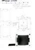
Using Parchment baking paper for the layout template which is kind of stiff and translucent which helps- I made a trace of the output transformer cutout using the chassis from the AA-100
 

Attachments

  • IMG_5114.JPG
    IMG_5114.JPG
    112.4 KB · Views: 23
  • IMG_5115.JPG
    IMG_5115.JPG
    74.9 KB · Views: 22
Last edited:
Heathkit AA-100 output transformer cutout tracing from an AA-100. This might help someone doing the cutouts for the AA-100 OPTs. Included a scale on top if you want to print it out and use it to trace on the chassis.

AA-100 Transformer Cutout.jpg
 
I usually use a hook splice (https://www.instructables.com/How-to-Do-a-Hook-Splice) because I tin stranded wires first before splicing, and it's harder to do a true Western Union splice after the wires have been tinned. I use needle nose pliers to bend the hooks and to crimp the hooks together after interlocking them. I then wrap the wire ends around with the needle nose pliers before soldering the joint again. Then slide on your heat shrink tubing and shrink it down.

I think its fine to use your 60 year old power transformer assuming it checks out okay and meets the voltage and current requirements you need.

Unless I'm missing what you're asking about the dual filament windings being ideal for dual EFB, the EFB installation on the Fisher SA-100 clone does not actually use the filament windings to power the EFB circuit. However, the filament winding is conveniently "referenced to ground" through its center tap via the 43V DC voltage divider from the screen voltage source.

Dave will need to comment on why he recommends dual EFB in this amp, but I’m pretty sure the main reason is to limit heat dissipation in the 337 regulator itself.
 
His suggested and hopefully upcoming revision uses two EFBs so each pair can be adjusted instead of all 4 at once- that is my understanding. Could be a current issue, but he has used one EFB for a quad before.
Appreciate the hook splice suggestion- I will go with that and tin beforehand. Decided on a new PT- not sure when I will downsize and need to make the amp durable- nothing wrong with the old transformers.
Saw a good trick for a drill press bed when drilling chassis- adding a large sheet of wood so the chassis doesn't tip and rock. Especially important with a 10 X 17 one.
--------------------------
 

Attachments

  • IMG_5120.JPG
    IMG_5120.JPG
    125.7 KB · Views: 12
Last edited:
George,
Be careful offering to sell anything in a discussion thread. AK rules say only in Barter Town and you have to be a subscriber for that. You could get your post deleted by a mod.
Sorry,
John
 
Thank you nerdorama- I will delete the offering for

- AA-100 power transformer or the
- Hammond PT (646 VAC CT no load, 6.3 CT, 5 VAC).
-Hammond (1441-30BK3) steel 10X17X2 chassis with steel bottom plate (1431-30BK3)
 
Not a problem John- hanging fire for now- I have had most of the parts since November. Eager to get things going.
 
Back
Top Bottom