• The move to the new server is done. There are some software and database maintenance updates in process. This has us passing the hat around to help out. We appreciate any donations. Seriously, even a dollar helps. The payment page may be found here - https://www.audiokarma.org/support.html

Teaser Pics -- Fisher SA-100 clone in progress

Dave,
Thanks very much for sharing your experience with the 51-58 transformers made by Mid-West Coil. Based on your experience I can now proceed without sweating the non-Stancor transformer source. I have an oscilloscope and will check for the oscillation at 20Hz that you addressed in your AA-151. (I also have a pair of “genuine Stancor” 51-58 transformers that I will compare). Interesting to note that your AA-151 was fitted with 51-58 output transformers, because the OEM stock was the 51-29 transformer, I believe.

Thanks also for reminding us of the two additions to the original EFB™ circuit, as used in your AS-100 clone. In my case I will use the stock AA-100+power transformer which has a 50Vac tap for a fixed bias supply, like you used in the Fisher 400 EFB mod for example.
 
Wow - Clearly some early morning brain fog in my last post! My Midwest coil experience was with the 51-29 transformers that were in that AA-151. I've looked at my notes and don't see that I've had any experience with Midwest's version of the larger 51-58 transformer. That being said however, based on the performance of their smaller transformers, I wouldn't be overly concerned with using their larger offering, as I have used other transformers of theirs in other applications, and had no issues with them at all. I'm sorry for the confusion this caused, but again, I think the outcome will be fine.

Dave
 
That's funny I was just checking the same thing on my UA2 Acro project, definitely a 51-29 OT.
 
I am starting to do some catch-up since my wife has been in the hospital and haven't looked at any of this in over a month and a half.
Dave, Can I pester you to shoot a few pictures of the input/output side and straight look down?
Question for all- I have an aluminum chassis and a steel one- one better than the other? I have read that steel can cause weird interactions with eddy currents. Urban myth?
I have all the parts and for my mental health need to start on this project. I got a nibbler for the transformer cutouts- I am hoping that will be better than a saber saw. Found a nice set of larger Greenlee punches on Ebay.
Spantou- have you made any progress or are we in the same boat?
 
No progress recently. Alas, I’m lazing away my winter in Florida. Sorry to hear about your wife’s hospital stay. Best wishes.
 
I am somewhat tempted to sell all the pieces and parts to someone who may want to do this project. I have everything needed, but doubt I can break even. I get to it- hard to work on things when my wife is in long-term care for a broken arm- not life-threatening, but been in for 3 weeks. It was a bad one- pins and so forth. She will be OK, but will take time.
 
With a number of members working on some version of this amp -- either by way of circuit, use of Fisher transformers, or just that it's a 6BQ5/7189 amp, I thought I would mark my progress on my own version of this great amp.

I had mentioned the basic features in a thread kpaxfaq started for his build, but started a separate thread so as not to trample on his. And while the goal is to build a worthy copy of the Fisher product, my build contains enough "deviations" as it were to possibly appeal to a broader group, so I've posted the thread here -- but the moderators can decide as they will which forum it is best suited for.

The basic features include:

1. Fisher X-101ST power transformer and AC power cord from same (the latter to ensure authentic Fisher sound). :)

2. Retains GZ34 rectification (as used by the X-101), with adequate choke and capacitance filtering to handle the full power needs of both channels at once.

3. Revised tube lineup, using a 6FQ7 inverter and ECC83 input stage for improved inverter drive, and elimination of 7247 issues. Both tubes obviously handle both channels.

4. Heath AA-100 OPTs to produce performance at least equal to the original devices.

5. Application of EFB(tm) to a pentode output stage for bias, featuring traditional bias/balance adjustments for both channels using only one EFB regulator.

6. Extending the EFB concept (simplicity, with superior regulation that automatically adjusts to prevailing conditions) to power the screen grids, with the added benefit of eliminating the space heater capabilities of the original design.

The goal is to not only meet, but with the application of EFB II (for pentode operation), improved on the performance of the original design, while still retaining that wonderful 6BQ5/7189 sound.

The pics show the mechanical progress. From left:

1. Getting the layout right. Planning is everything.

2. Measure twice, cut once.

3. Just like a classic kit, layout the parts (mechanical only at this point) to make sure they're all there (tubes are dummies for show).

4. Everything mounted up ready for wiring.

5. The Principle Engineer (Banditt), simply exhausted from all the details of the project.

This will ultimately end up in a new article detailing the build, and spotlighting operation of EFB II, that is to be published on the Tronola website later this year -- but for now, I thought it would be neat to share the development process of the project with AK.

Family is in town this week, so the start of wiring will be delayed. I'll update the thread as progress continues......

Have a safe holiday --

Dave
i like the 3rd photo very clean looking work. photo 4 thats the boss right ? LOL
 
Thanks for the kind words. Principle Engineer Banditt passed away about 4 1/2 years ago (RIP), but was an intrigal part of this and countless other projects over the years. This project was always one of his favorites based on all the various systems he would curled up and listen to...........

Dave
 
High praise indeed. Sorry he’s no longer there to help with listening to the tweeks you are working on.
 
Mapping out the pinouts and which pots do what. Does this look like the best assignment of each of these pots?
 

Attachments

  • IMG_5102.JPG
    IMG_5102.JPG
    114.3 KB · Views: 31
  • IMG_5103.JPG
    IMG_5103.JPG
    67.2 KB · Views: 31
With a number of members working on some version of this amp -- either by way of circuit, use of Fisher transformers, or just that it's a 6BQ5/7189 amp, I thought I would mark my progress on my own version of this great amp.

I had mentioned the basic features in a thread kpaxfaq started for his build, but started a separate thread so as not to trample on his. And while the goal is to build a worthy copy of the Fisher product, my build contains enough "deviations" as it were to possibly appeal to a broader group, so I've posted the thread here -- but the moderators can decide as they will which forum it is best suited for.

The basic features include:

1. Fisher X-101ST power transformer and AC power cord from same (the latter to ensure authentic Fisher sound). :)

2. Retains GZ34 rectification (as used by the X-101), with adequate choke and capacitance filtering to handle the full power needs of both channels at once.

3. Revised tube lineup, using a 6FQ7 inverter and ECC83 input stage for improved inverter drive, and elimination of 7247 issues. Both tubes obviously handle both channels.

4. Heath AA-100 OPTs to produce performance at least equal to the original devices.

5. Application of EFB(tm) to a pentode output stage for bias, featuring traditional bias/balance adjustments for both channels using only one EFB regulator.

6. Extending the EFB concept (simplicity, with superior regulation that automatically adjusts to prevailing conditions) to power the screen grids, with the added benefit of eliminating the space heater capabilities of the original design.

The goal is to not only meet, but with the application of EFB II (for pentode operation), improved on the performance of the original design, while still retaining that wonderful 6BQ5/7189 sound.

The pics show the mechanical progress. From left:

1. Getting the layout right. Planning is everything.

2. Measure twice, cut once.

3. Just like a classic kit, layout the parts (mechanical only at this point) to make sure they're all there (tubes are dummies for show).

4. Everything mounted up ready for wiring.

5. The Principle Engineer (Banditt), simply exhausted from all the details of the project.

This will ultimately end up in a new article detailing the build, and spotlighting operation of EFB II, that is to be published on the Tronola website later this year -- but for now, I thought it would be neat to share the development process of the project with AK.

Family is in town this week, so the start of wiring will be delayed. I'll update the thread as progress continues......

Have a safe holiday --

Dave
I did taw a puddy tat!
 
I found the completed amp photos- sorry for the requests for those. Have enough to get going- I think I can look at those and figure out which potentiometers should perform what function. Layout can sink a good circuit so trying to plan ahead. I posted a sketch in post #150 if anyone can check it. Thanks!
 
GG -- The controls between each pair of output sockets should be the DC Balance controls, the two controls on either side of the 6CG7/6FQ7 are the AC Balance controls, while the two controls at the side of the chassis should be the EFB™ Bias Trim controls.

My build also included two additional controls, a Screen Voltage Adjust control, and an EFB Bias Range control. Please understand however that this amplifier -- as much as it was intended to be a high end use device -- was also a bit of a proving ground for the idea of using one EFB reguator, while also allowing for the adjustment of each output tube's individual quiescent current. As such, the amplifier was control heavy, but served the purpose well for the trials of that concept.

Looking at the date that this project originated from, it's now been over 10 years ago since I built it. It still gets a lot of play and enjoyment, with the only two modifications made during that time being the addition of the protection diodes and shunt resistor added to the EFB regulator circuit to bulletproof its dependability. The original regulator is still in place having never failed in this amplifier, but received the additional components as a result of my work in determining why a handful of regulators had failed in the Dynaco SCA/ST-35 setting. With that issue fully resolved, I went back and added those components to this amplifier as well since they are now considered standard items for any EFB cathode regulator circuit.

Given the time and use experience now had however, were I building the amplifier again, I would now eliminate the two EFB Bias Trim controls and the Screen Voltage adjust control, and then build the unit with two EFB cathode regulators -- one for each channel. This move has nothing to do with any potential performance increase, as there would be none from this move. As a design exercise, it proved that the desired outcome of being able to control each tube's quiescent current individually while only using one EFB regulator could be accomplished. But it also resulted in a higher control count and greater complexity in the bias adjustment procedure, that time has shown to be less desirable than simply just using two regulators. By using two EFB regulators and fixing the screen grid voltage at the (now known) optimum value, it would result in a very typical control layout and adjustment procedure, with the unit then employing just 2 AC Balance controls, 2 DC Balance controls, and 2 EFB Bias Controls. But either way, the unit delivers the same performance levels in all respects whether the original design with one regulator is built, or is modified to employ two.

Dave
 
Thank you so much for the update on how to execute this build. I have quite a bit invested in all the parts and transformers so I am proceeding cautiously to start the construction. Unfortunately, I am not able to take out the items you mentioned and redesign the circuit so at a loss for what to do to get across the finish line. I am not sure if Spantou has the skills to redraw the circuit with these suggestions in mind; I know he is planning on doing one himself. I don't know how many people are watching this thread, maybe someone can help.
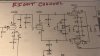
Dave - don't suppose you made a new schematic drawing with the changes?
I can see how to use two EFB circuits for each channel, but not sure where to insert it after the center tap of the filament winding. If I take out the screen voltage adjustment- not sure how to configure what looks to be a voltage divider around the FQP9N50C. So maybe forge ahead and build it as the original schematic shows despite its complexity?
I think I will stick to pre-amps after this...
 
Last edited:
Mr. Griswold,

IIRC you said you are using the power transformer (PT) of the Heathkit AA-100 as well as the OTs. The AA-100 has a convenient 50V tap for a bias supply. When DG built his prototype he used an available Fisher PT without a bias tap, and as a result went for the single cathode EFB regulator with a slightly positive charge on the control grid of the output tubes for DC adjustment purposes. With the available bias tap on the AA-100 PT, I plan to use the negative control grid EFB scheme Dave used in his later Fisher 400 mod here, where the cathodes are grounded (via a small value resistor for measurement purposes). https://audiokarma.org/forums/index.php?threads/improving-the-fisher-400.511867/

One will have to fiddle with the power supply as a result, to maintain the plate to cathode voltage Dave designed for, but that should not be a problem. Due to the similarities in requirements, Dave’s Fisher 400 mod will be my guide on the EFB side, while maintaining the operating conditions and feedback for his SA-100 clone. I have not run through the calculations for the regulator and EFB, but I expect the values Dave used for the Fisher 400 mod will work for the SA-100 clone. I’m on vacation through February, and will start working on this in March. I will be happy to work through the details with you then.

If you prefer the cathode bias scheme Dave talked about in post #153 you could simply use the Maggie 9300 scheme you suggested in post #155, one regulator for each output tube pair. Applying the bulletproofing Dave mentioned in #153, of course.

The nice auto bias board Erhardt Audio sells is an alternative, but that will NOT be EFB since it will clamp the bias current to the set value, rather than maintaining a fixed ratio between the plate voltage and applied negative bias. I actually have a couple of those waiting to be used in a future amp, but how it will interact with the “magic” Dave designed into the SA-100 clone is unknown, and for my SA-100 clone I will use Dave’s EFB.
 
Last edited:
Mr. Griswold,
,
IIRC you said you are using the power transformer (PT) of the Heathkit AA-100 as well as the OTs. The AA-100 has a convenient 50V tap for a bias supply. When DG built his prototype he used an available Fisher PT without a bias tap, and as a result went for the (mostly) cathode EFB with a slightly positive charge on the control grid of the output tubes for DC adjustment purposes. With the available bias tap on the AA-100 PT, I plan to use the negative control grid EFB scheme Dave used in his later Fisher 400 mod here, where the cathodes are grounded (via a small value resistor for measurement purposes). https://audiokarma.org/forums/index.php?threads/improving-the-fisher-400.511867/

One will have to fiddle with the power supply as a result, to maintain the plate to cathode voltage Dave designed for, but that should not be a problem. Due to the similarities in requirements, Dave’s Fisher 400 mod will be my guide on the EFB side, while maintaining the operating conditions and feedback for his SA-100 clone. I have not run through the calculations for the regulator and EFB, but I expect the values Dave used for the Fisher 400 mod will work for the SA-100 clone. I’m on vacation through February, and will start working on this in March.

If you prefer the cathode bias scheme Dave talked about in post #153 you could simply use the Maggie 9300 scheme you suggested in post #155, one regulator for each output tube pair.

The nice auto bias board Erhardt Audio sells is an alternative, but that will NOT be EFB since it will clamp the bias current to the set value, rather than maintaining a fixed ratio between the plate voltage and applied negative bias. I actually have a couple of those waiting to be used in a future amp, but how it will interact with the “magic” Dave designed into the SA-100 clone is unknown, and for my SA-100 clone I will use Dave’s EFB.

All the auto bias module requires is a suitable -ve DC bias supply, anything from -50VDC up to -120VDC, the 6.3VAC filament supply and some minor mods to the output tubes wiring. That is the beauty of the auto bias module, it is really quite simple to install into pretty much most tube amps, PP or SE.
Also, if the amp does not have a -ve DC filament supply, other auto bias module models come with their own 'on board' bias supply, so different models of the auto bias models will pretty much suit most tube amp designs.
Perhaps Dave could chime in here with regards to an external auto bias module as an alternative. I do not see any issues using the auto bias module in this amp here, but verification from Dave would help for sure.
 
Last edited:
Back
Top Bottom