• The move to the new server is done. There are some software and database maintenance updates in process. This has us passing the hat around to help out. We appreciate any donations. Seriously, even a dollar helps. The payment page may be found here - https://www.audiokarma.org/support.html

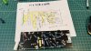
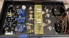
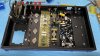
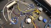
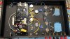
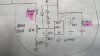
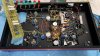
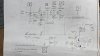
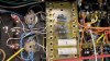
Teaser Pics -- Fisher SA-100 clone in progress

His suggested and hopefully upcoming revision uses two EFBs so each pair can be adjusted instead of all 4 at once- that is my understanding.
Ah, I went back and reread post #153, which I perhaps misunderstood earlier. It looks like I had my orientation flipped. If the Bias adjustments were removed (the points labeled C in schematic) in favor of keeping just the EFB Range adjustment (the point labeled D in schematic), and if you allowed an appropriate range to be dialed, and if dual EFB regulators were employed, you would have the means to independently adjust bias per output stage channel, and with a side benefit of dissipating half of the heat of using a single 337 regulator. Clever.

Well anyway, now I am curious to see the dual EFB schematic...
 
Last edited:
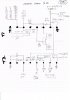
OK -- Finally had a chance to draw something out, but a number of comments would be useful for those following along:

1. This project was my first effort at providing individual adjustment capability for all four output tubes while using one EFB™ regulator, and while it works just fine, time has shown that the adjustment process it requires is more tedious than I would like. That's partially because I intentionally included more adjustments for experimental purposes, and partially because of the configuration itself. Converting the adjustment procedure to a more conventional process could be accomplished a couple of different ways, but the most practical way of doing it is to simply use separate EFB regulators for each channel.

2. One approach would be to eliminate the EFB Range Control and fix it at a preset value, and then build more range into the existing bias controls that supply point C to each channel. This approach would allow to continue using just one EFB regulator to support both channels. The downside of this approach however is that to accommodate a usable range for typical tubes means adding more (potentially unneeded) voltage drop across the EFB regulator which it can certain handle (particularly with the new "bulletproof" measures applied), but goes against my approach of over-rating and under taxing SS devices. This is the reason that the EFB Range Control was included in the first place.

3. Ultimately then, the move to use dual EFB regulators has nothing to do with over taxing a single regulator for the amplifier. Even before the bulletproofing measures were added, continuous operation of both channels at sustained maximum power output caused the regulator to pass less than 15% of its rated current handling capability, at less than half of its rated voltage handling capability, and dissipate less than 3 watts in a worst case scenario. For a metal TO-220 device rated for 150˚C operation, it was uh, a walk in the park for the conditions it was operating under. With the bullet proofing measures in place, total worst case current passing through the regulator is now less than 8% of rated capability, and dissipation is reduced to just over 1.5 watts under a worst case scenario. As well, with the diode protection pack added that I developed and discussed in my bullet-proofing thread, the turn-on stress condition #2 identified in that thread is eliminated as well (stress condition #1 does not exist in this amplifier). So the choice to move to dual EFB regulators has nothing to do with relieving any normal operating stress on a single regulator design, and everything to do with being the most practical way to achieve a more conventional adjustment approach end. With dual regulators, the range of the DC Balance controls will allow for any reasonably good tubes to be easily balanced out, while allowing the EFB Regulator itself to set the bias voltage for the tubes eliminates any otherwise needless voltage drop across the regulator element.

4. In the sketch provided then, not only is the use of dual EFB Regulators shown, but included is the bullet-proofing elements now standard for all cathode-injected EFB designs, and some other improvements/conveniences in addition as well. Those include:

A. The Screen Grid Voltage Adjustment control has been eliminated, and fixed values shown for its replacement.

B. The power MOSFET used in the EFB Screen Grid Regulator now includes a 1K gate stopper measure -- not because it needs one, but because it is simply good design practice.

C. The power MOSFET is now partially bypassed which reduces its worst case dissipation to under 4 watts under full sustained power output in both channels. Under normal operating conditions, dissipation of the device is just over 1 watt.

D. As a result, I can now specify an STF10NK50Z device (or equivalent) for the MOSFET element. This is a 500 volt, 9A, 30 watt plastic device that (again) is significantly over-rated for the service it performs. In addition to no longer needing any insulated mounting hardware (because it's plastic), this device no longer requires the use of the Zener protection diode shown in the original schematic, either.

E. Note the value of the dropping resistor providing B+ to the AF Amplifier stage has been increased, and voltages shown as delivered to the phase inverter and AF Amplifier stages altered accordingly. The new voltages properly (i.e., better) center the operating parameters for optimum performance from the inverter stage.

Do note that NONE of these changes alter or improve the measured performance of the design as originally published. They are simply an update given for all the various reasons cited, as slowly applied over the last decade since the project was initiated.

That should about do it. I truly appreciate all the interest in the design. I am always loath to heap any praise on any of my own work, but this design remains on of my most favored amplifiers to listen to. The fact that it has remained so since the project started is the take away point to understand.

I hope this helps --

Dave
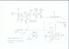
SA-100 Clone Update.jpg
 
A million thanks Dave- We owe you a steak dinner. I can now go ahead with my build after a week or so just to let any dust settle.
Like the dual EFBII™ approach!
This is very helpful and much appreciated.
George

Note:
The MOSFET you listed is listed as discontinued, but this one looks comparable- with specs a tad higher in each parameter.

*** NB- Dave pointed out this device does not have a plastic tab so you will need an insulation kit.
600 V, 10A, 35 Watts***

https://www.digikey.com/en/products/detail/stmicroelectronics/STF12NK60Z/954101

SA-100 Clone Update.jpg
 
Last edited:
Specs wise it is certainly quite good, although I doubt it's a plastic device. Not a deal breaker, but just something to be aware of......

Dave
 
I noticed that- I have insulating parts coming- one step forward one step back!
They make a plastic tab version but could not see how to order that type-
no biggy to insulate.
As in the 9300 EFB is it OK to have the LM337 tab attached directly to the chassis- no insulation?

Breaking with how I have done things before decided to sketch out how I am doing the terminal strips. Glad I did! Checked it a few times. Will review it with fresh eyes down the road. Using two 8 lug strips with Ground at each end.
EFB gets a 5 lug with center tab as ground. Won't rely on the chassis for a good ground- thinking a copper bus down the middle as a common ground. My thinking is to build the terminal strips partially and then determine the best layout as I go.

Admire the skill and knowledge Dave has to design this update.
Terminal Boards- Fisher Clone0001.jpg Terminal Boards- Fisher Clone.jpg
 
Last edited:
If anyone has started V1 of this I have the MOSFET and a few other components that you may not have in your parts bin
- shoot me a message.
Got my OPT cutouts done.
 
Made a lot of progress
- made a turret board for the power and EFB
- Used a terminal / tag board for the circuit that goes from the 6FQ7 to EL84.
- Used small terminal strips that go on either side of the 12AX7 and the 6FQ7 for a few components.

Can I get opinions on the placement of the Power and EFB board? It would free up a lot of room if I put the power and EFB board directly on the other side of the power transformer and choke. Do you think any transformer flux would wack out the function of the circuits?
I may be able to move it to the other side of the can caps, but this makes things easier.

Space saving option: Thinking about going with a SS rectifier (two diodes like a 5AR4) and putting the filter caps
underneath. I have a time delay circuit already built.
That 17 inch long chassis gets eaten up pretty fast!

Planning on running a ground bus down the middle, or I can get lower to a star ground with more wire runs. Yes? No?

Thanks for any input on this - George
 

Attachments

  • IMG_5153.JPG
    IMG_5153.JPG
    116.9 KB · Views: 45
  • IMG_5152.JPG
    IMG_5152.JPG
    123.3 KB · Views: 44
  • IMG_5156.JPG
    IMG_5156.JPG
    138 KB · Views: 44
Last edited:
Made a lot of progress…..

Space saving option: Thinking about going with a SS rectifier (two diodes like a 5AR4) and putting the filter caps
underneath.

Looking good! Excellent progress.

If you use SS rectification I think those big blue filter caps will look great spaced symmetrically across the centerline on top. It is more work, but I think to my eye the top plate will look a bit too empty if the caps are hidden underneath.
 
I am holding off on final placements until I can ascertain that it is OK as I suggested. Anyone else have any input?

I did find this online electronics store when I was looking for a few of the non-standard values- https://www.soniccraft.com/index.php
They have 91K and 300K 1W resistors. And other useful things.
 
Last edited:
I am holding off on final placements until I can ascertain that it is OK as I suggested. Anyone else have any input?

I did find this online electronics store when I was looking for a few of the non-standard values- https://www.soniccraft.com/index.php
They have 91K and 300K 1W resistors. And other useful things.
Thanks for that site info! I had never heard of them. Just placed a resistor order with them so, thanks again!
 
Chassis drilling and machining is underway. That 17-inch length goes fast!
It all fits.
Note about that MOSFET- it is in an all plastic case.


IMG_5221.JPG
 

Attachments

  • IMG_5223.JPG
    IMG_5223.JPG
    124.3 KB · Views: 25
Last edited:
Looking great! Excellent progress. Those transformer cutouts look professional. How did you do them?
 
Last edited:
Looking great! Excellent progress. Those transformer cutouts look professional. How dis you do them?
I used a fine tooth sabre saw. Mark corners and go in 3/16 towards the center allowing for 3/8 holes on each corner- then cut. And a bunch of filing. Everything seems to be fitting together, so so far so good. Did not get any messages or any posts that red-flagged anything so far. This is the fun part. I finally built a dim bulb tester (good to condition the caps too), also put one of those little volts, amps meters in a duplex outlet box. Figured this wasn't the project to plug and pray.
 
My question as I continue wiring up the amplifier- To have the bias INCREASE turning clockwise on the 5K pot which way should I wire the ends of the Pot? Thinking the closer to the 15K the less the bias- just a stab in the dark.
I am days away from firing the amp up, but thinking having all the pots at mid range. I need to read back and see what Dave suggested for setting the DC and AC balance. With EL-84's out I should be able to measure the bias, right? 15.4V?

IMG_5253.jpg

Coming right along- the center is not as neat as I would have liked, but some of the wire runs were done to avoid cross interference. The turrets really help keep things straight and don't have lots of component to tube socket connections- just my preference.
 

Attachments

  • IMG_5254.JPG
    IMG_5254.JPG
    132.4 KB · Views: 18
Last edited:
Went through the schematic and checked off all the connections and they seem OK. It was brought up on a Variac- to 122 VAC. No smoke so that's good. Drawing .94 Amps, 102 Watts-I have a 2.5 amp fuse inserted.
Voltage readings are tracking correctly from E, 447 VDC all the way to AF Amp down around 188 VDC, so good there.
Had to add a 20ohm 10 Watt to drop the B+ since I am using a SS rectifier. So a total of 50 ohms dropping.
I have attached a few of my working schematics (5280 thru 5282)

Have the AC and DC balance happy and set.

Big Problem- Could use some help with this one-
1. Wicked motor boating when I connect any source (preamp or signal generator at 1Khz)- dead quiet with no input connected. Tried a .1 UF cap in the 12AX7 input in series with the 10 K- same problem, since removed.
I have a sound file on Google drive: https://drive.google.com/file/d/1aEFZS75Ty5ade_JPVHAsK7aCFMlgKSoS/view?usp=share_link
Don't know if it is relevant- I used the same values for L/R on the Cap and Resistor that are referred to in the notes- the C and R in series off of pin 1 on the 12AX7. 150 pF and 2.2K ohm.

Fixed- Bias was stuck at 17 VDC on Right Channel- Duh, had the wrong resistor to Pin 1 to the LM337 Ch2. 91K Not 300 K. Solved.

So that's where I am- I will continue troubleshooting and researching motorboating solutions but any observations are welcome. If I can lick the motorboating I will be in good shape.
Thanks,
George
 

Attachments

  • IMG_5280.jpg
    IMG_5280.jpg
    70.1 KB · Views: 35
  • IMG_5281.jpg
    IMG_5281.jpg
    79.9 KB · Views: 32
  • IMG_5282.jpg
    IMG_5282.jpg
    81 KB · Views: 32
  • IMG_5285.JPG
    IMG_5285.JPG
    155 KB · Views: 32
  • IMG_5286.JPG
    IMG_5286.JPG
    146.6 KB · Views: 33
  • IMG_5254.JPG
    IMG_5254.JPG
    132.4 KB · Views: 34
Last edited:
Went through the schematic and checked off all the connections and they seem OK. Brought up on a Variac- to 120 VAC. No smoke so that's good.
Voltage readings are tracking correctly from E, 447 VDC all the way to AF Amp down around 188 VDC, so good there.
Had to add a 20ohm 10 Watt to drop the B+ since I am using a SS rectifier. So a total of 50 ohms dropping.
I have attached a few of my working schematics (5280 thru 5282) - Does anyone see anything wrong here?

Have the AC and DC balance happy and set.

Big Problem- Could use some help with this one-
1. Wicked motor boating when I connect any source- dead quiet without one. I have a sound file on Google Drive- https://drive.google.com/file/d/1aEFZS75Ty5ade_JPVHAsK7aCFMlgKSoS/view?usp=share_link

My Problem-
I will keep checking but stuck on this one.
Bias is stuck at 17 VDC on Right Channel- the adjustment pot not affecting the bias output from the LM337T. Likely a wiring issue since L channel is adjusting. Checked the wiring 20 times- guess I need to take a fresh look in an hour or so. Sometimes we see what we want and overlook the obvious. Part of the process. Maybe popped the regulator?
1-ADJ, 2-IN, 3-OUT TI LM337T.
(see IMG-5285.JPG)The orange and black wires are the two ends of the bias adjustment pot (go to the 300 Ohm and the 15K), Blue wire going to pin 1 is the wiper of the 5K Pot.
(Picture 5286) the white wire from pin 3 of the LM337T output goes to two 10 ohm resistors and each goes to pin 3 of the output EL84s.

So that's where I am- I will continue to troubleshoot, but any observations are welcome.
Thanks,
George
I think your output transformer primary probably needs to be reversed for polarity, you're getting positive feedback rather than negative feedback.
 
Back
Top Bottom