• The move to the new server is done. There are some software and database maintenance updates in process. This has us passing the hat around to help out. We appreciate any donations. Seriously, even a dollar helps. The payment page may be found here - https://www.audiokarma.org/support.html

Teaser Pics -- Fisher SA-100 clone in progress

A lot of amps just run the center tap or the negative side of the rectifier to the chassis, then use the chassis for making electrical 'ground' connections throughout the amp. This was pretty common practice in many of the 'console' type amps, as well as many of the 'entry level' offerings. A lot of the 'better' amps isolated the electrical ground from the chassis. If you have no 'chassis' ground, then there will be some kind of 'ground scheme' or 'ground buss' throughout the amp. In tracing where the power supply presents the negative DC ground path, you can begin to follow all the varying connection points throughout the actual construction and 'physical' part of the circuit (as in the actual wires and lugs, etc). This is often 'tricky', as some of them get 'daisy-chained' from point to point, while others are more of a 'star' ground; one central location with ground wires going off in all directions under the chassis. Or, the 'buss' type ground where there is simply a single grounding wire running throughout the amp and all the circuit grounds attach to it. I guess this is just a matter of design choice or manufacturing needs. Sometimes the tail wags the dog, and what engineers and designers say HAS to happen, get's tossed out for what 'CAN' happen as related to assembly potential. Anyway, I've seen commentary on the benefits and detriments of all these different ways to run 'ground' in an amp. I'm pretty sure that from a purely technical standpoint the ground isolated from the chassis, and as distant from the actual 'amplification' section of the circuit is probably the best from a signal purity standpoint. Also probably the most difficult to achieve in construction. Honestly, most of what I've built has used a chassis ground, which admittedly does intermix the electrical DC ground of the amp with the 'signal' ground coming in from the source. As yet this has not caused me any real issues to have to deal with. But, I also have to say that when I see some of the absolutely beautiful jobs of construction some of the people here on AK have done with their amps and the grounding schemes, I'm humbled!! It's like electronic 'art' to me! I wish I had the patience and foresight to build a project at that level. Maybe as I get better at it.
 
In all vintage equipment, circuit ground and chassis ground is one and the same, and the equipment was supplied with two wire non-polarized AC line cords. It is that way with the Fisher clone amplifier of thread. If a virtual ground was needed, then AC bypass caps were employed. As equipment then became adapted to the advent of the 3 wire power system with ground, it then became viable to disconnect these two ground systems: Circuit ground could be isolated from the chassis, while the chassis could be grounded through the AC ground system -- a neat way to prevent ground loops and achieve minimum noise at the same time. As manufacturing techniques changed, the "chassis" became plastic, so that all the AC ground system was connected to was the frame of the power transformer and possibly a metal cover and/or bottom plate -- but the circuit ground is isolated.

As a side note, it is usually poor procedure to modify vintage equipment originally supplied with a two wire power cord, to employ a three wire AC power cord that connects the chassis directly the power grid ground -- in the name of safety. Aside from the possible ground loops that can create with other equipment whose circuit ground also operates at AC ground potential (cable and sat boxes), it can also inject unwanted noise as well. For those vintage units that employ an AC bypass cap, it is best to replace that cap with a modern fail open cap, and install a 2 prong polarized AC line cord that has the bypass cap connected to the neutral side of the line. That way, circuit ground and chassis ground can be maintained, and a virtual chassis ground connection to the AC ground system can be maintained in the safest possible way.

Dave
 
I have most of the small parts for my build. Ordering the chassis tomorrow from Mouser. And the MOSFET, 1% resistors. I was thinking about using the pots that have a screwdriver slot on the end of the shaft instead of using knobs- good idea, or not? Nobody has said anything so OK to order 1/2 watt pots all around?
I don't think it matters, but thought I would ask: if I use SS rectification do I still want to include the choke?
The electrolytic that is right off of the EFB range control- is that a 4.7 or a 47 uF cap?
Looking for suggestions to source panel mount RCA and speaker terminals- I know the usual suspects from Amazon, Amplified Parts to Mouser. I see that Dave used through-hole barrier strips. Amazon RCA's have been a disaster. To be honest I have had great results with the Switchcraft nickel ones, but doesn't have that hi-fi OFC vibe.
Thanks for any help with the above and any Ideas are welcome.
 
Last edited:
Hi George,

While we allow the experts to enjoy their Thanksgiving dinners I will give my take on the questions. Since I have not started my SA-100 clone build I have an interest in the right answers too and shall appreciate correction if necessary.

1. Potentiometer wattage - 1/2 watt pots are fine. I checked and the AC balance in the cathode of the 6FQ7 has the highest dissipation of around 0.1 watt.
2. Is the choke necessary with SS rectifiers - I think it is equally necessary and I plan to have the choke.
3. Hard to see in the schematic, but the EFB range control cap is a 4.7 uF, based on the similar circuit in Dave’s Dyna SCA EFB. (http://www.tronola.com/SCA35-EFB-R02_Assembly.pdf)
4. RCA and speaker connectors are “personal preference” items. I second Switchcraft and usually prefer sturdy construction over bling, buy Rhodium plated connectors when I can afford them.
 
Changed my mind (for now) and going to give it a try.
If I use the AA-100 PT there are no center taps on the filament windings so wondering if I can do a pair of 220 ohm resistors from each leg of the 6.3 VAC to feed the Bias EFB circuit?
Which pots are the higher current ones? I see two Allen Bradley J types. Looks like the two 5K bias adjustments.
B+ is higher so saw a brief mention about that but no posted solution.
Kind of out on a limb here...
Has anyone used all 3 transformers from the AA-100 to build this?

I plan to use the AA-100 power transformer in my clone build and see no issue with the heater coils without center tap. The original AA-100 had a 2k hum pot in each. I noticed that Dave lifts the centertap of the clone heaters to 47 volts, which I will observe.

The HV secondary on the AA-100 PT at 760 VCT is a bit higher than the 720 Vct Fisher PT that Dave used, but it includes a 50Vac tap for a negative bias supply. I too plan to use SS rectifiers and will depend on a psuedo-choke input supply, with an smallish foil capacitor at the choke input to adjust the voltage, and a resistor thereafter to get B+ to the desired 430 Vdc. I aim for 430 Vdc because with the available 50 Vac tap I plan to use a regular EFB scheme, not the mixed-cathode bias in Dave’s clone build.
 
Thanks spantou01- appreciate the info. I used Parts Connexion Rhodium when I did my 2 McIntosh MC-60's. Might get a pair for this build.

Enclosure:
16X8X3 https://www.mouser.com/ProductDetail/546-1441-28BK3
Hi George,

Double check you layout plans with a 16x8 chassis, if you intend the layout of two output transformers with the orientations the two Daves used. Looking at photos of the built clones I think 8 inches width might be a bit tight. Dave451 said he used a 17x10x2 chassis and the width looks about perfect.
 
Last edited:
Double check you layout plans with a 16x8 chassis, if you intend the layout of two output transformers with the orientations the two Daves used. Looking at photos of the built clones I think 8 inches width might be a bit tight. Dave451 said he used a 17x10x2 chassis and the width looks about perfect.[/QUOTE]

Thanks for pointing that out! - last thing I need is too little room. Are you going with steel or aluminum? I think steel might be best because of the transformer and choke weight.

I might reconsider my transformer choice- I like the simple EFB idea. Have you sketched a schematic for the bias part? Guess we could extrapolate that from the 9300 circuit he did.

Looking at this feedthru barrier strip for speaker connection. I would just do 8 Ohm with two terminals, but seems foolish not to have 4,8 and 16.
https://www.mouser.com/ProductDetail/538-38721-7304
 
Last edited:
The barrier terminal blocks you listed seem a bit “light duty” with a current rating of 1.5A, if Mouser is correct with the data. There are some higher current barrier block available, but I don’t see them now at Mouser. Maybe this one, but I’m not sure it is the right type.
https://www.mouser.com/ProductDetail/Molex/38711-2204?qs=kD7lmHUVEJafrdnCfWyrtg==
I don’t know what block Dave used.

Regarding chassis: I have a black powder-coated steel Hammond 17x10x3 in my storage closet that I plan to use.

Unfortunately I have not yet done the schematic for the “simple EFT” bias. I believe the Magnavox EFB mods that Dave did, like the 9300, were all cathode biased like the Dyna SCA35. Instead, look at Dave’s well-documented Fisher 400 mod with fixed, grid bias, and similar supply voltages as the AA-100 PT and SA-100 circuit voltage requirements. I will adjust from there.

https://audiokarma.org/forums/index.php?threads/improving-the-fisher-400.511867/page-4#post-6686863
upload_2022-11-24_22-30-7.jpeg

Fortunately AK member KWard has a nice thread on the calcs, to double check on required resistor values. See:
https://audiokarma.org/forums/index.php?threads/roll-your-own-efb-enhanced-fixed-bias.994694/
 
Last edited:
I meant to point out post #6 in the thread on “roll your own EFB” above. AK member thorpj generously provided a nice design package with the necessary Gerber files to have your own “helper PCBs” made for EFB, and a spreadsheet to calculate resistor values for a specific situation/application. https://audiokarma.org/forums/index...efb-enhanced-fixed-bias.994694/#post-15573728

thorpej stated that it was done with Dave Gillespie’s permission, so it should be fair to link it here and again mention that EFB is copyrighted by Dave and kindly shared with this community for personal use. My personal thanks to the two gentlemen for their generosity, and to KWard for explaining the calculations so well.

https://github.com/thorpej/Electronics/tree/master/Tube_Audio/Helper_Circuits/EFB_Bias_Supply

If you scroll down there are 10 steps for configuring the EFB board to your needs. I have not tried to use this information, nor made any PCBs yet. I’m not sure now to go about ordering PCBs from say PCBWay from China and exactly what files are needed, but I hope to learn and try it soon.
 

Attachments

I am going with Dave's original schematic- Seems easier to implement. I am committed now- just ordered all the parts yesterday. Got the transformers out of the Heathkit- sprayed a coat of Krylon Fusion Satin Black.
Need to score 2 6FQ7 tubes at some point- don't have any.
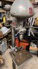
Feel a bit of trepidation with the metal work, I overhauled the drill press that my Dad had so set there. Make a tracing of the OPT cutouts so that should help.
Never found 300K ohm resistors so going with 330K.IMG_4921 2.JPG IMG_4923.JPG IMG_4922.JPG
 
Now THAT'S a drill press!

Thank you, my Father bought it around 1955- all metal- not one ounce of plastic. Replaced the bearings on the spindle, new chuck and did a teardown on the motor. Run out is now something like .001mm now. My Dad taught me mountains of things including working on motors and I have become kind of a turntable nut. Have a few Rek-O-Kuts, ARs, and a Thorens TD124II (also Dad's)- all overhauled, find it very satisfying.

If you have the time could I ask for a shot of the top of the amp looking straight down; that would help us (myself and Spantou01- both embarking on the project) with the layout. I will try blowing the picture up to a large format to use as a template. Also a shot of the back where the RCA and speaker connectors are- just want to get a glimpse into how you arranged things. Appreciate your hard work and sharing with us.
 
Beginning to begin. "No atheists in foxholes" Just did a quick throwdown of some of the parts. .Need to look at Dave's layout again.
My filament voltage is running at 6.8 with 122 line voltage. Should I put a regulator on that? Or will a full up running transformer produce less voltage. I have 6 tubes that require 6.3 each,, so thinking they might pull down the voltage.

IMG_4943.JPG
 
Those are the latest schematics I have seen. I’m a bit behind you but soon to follow (but see below) and it would be good to know if there had been any further tweeks or improvements to the basic circuit. Or could there be?

I have acquired a pair of AA-100 output transformers marked 51-58. The seller called them Stancor 51-58 transformers, but the manufacturer code is 549, in stead of 138 as expected for Chicago Standard Transformer. The 1961 EIA codes show 549 as Mid-West Coil And Transformer Co. Does anyone have experience with these transformers? Are they as good as the Stancor transformers and more importantly, will the feedback circuit work as Dave designed it for the clone SA-100. I know only someone that actually tried them will have the answer, but wonder if I should not return them to the seller.

They look identical in size (to the Stancor 51-58, but it appears the wire color coding might be different. Here is a picture showing the codes (faintly)
 

Attachments

  • 1CD1BC89-CDEE-4CEA-B3E5-9907F1AB93E5.jpeg
    1CD1BC89-CDEE-4CEA-B3E5-9907F1AB93E5.jpeg
    143.8 KB · Views: 18
Last edited:
Spantou,

Test data of the AA-100 transformers is in the linked topic, reply #5. Maybe comparison of what you have with that information can help you to decide.
https://audiokarma.org/forums/index.php?threads/aa-100-opt-inductance-help.835512/

I noticed some differences from the schematic. The primary impedance is 7700 in the schematic here while it is 7000 in that datasheet. Also , the primary side shows an extra winding there. If someone can clarify about these differences it shall help me as I am planning to have new transformers made for my own SA100 clone project.

Regards

Anwesh
 
Last edited:
Anwesh,

I have looked for Dave G’s thorough discussion of his measurements of the AA-100 output transformers, but could not find it yet. It is out there somewhere to be found!.

He measures the impedance ratio always from the full secondary, i.e. in the 51-58 that would be from the 16 ohm winding. That was how he determined the Primary impedance of 7700 Ohm. Since the 8 and 4 ohm taps can’t always be placed exactly, it might be 7000 Ohm at the 8 Ohm tap, and perhaps that is how Tom Bavis measured it.

I believe in Tom’s diagram he used a generic template where he wrote down the values where windings actually existed for the measured transformer. So, his diagram has values for two primaries and center tap as well as the 0-4-8-16 ohm secondary connections only, and the additional (unmarked) windings can be ignored.

You might find this discussion of the SA-100 interesting too:
https://audiokarma.org/forums/index...isher-sa-100-with-efb-ii.476431/#post-6168041
 
I have in fact had experience with the 51-58 transformers as manufactured by Mid-West Coil, and they are very good performers with excellent power response and HF transient (10 kHz square wave) response, but noted that they do show a small parasitic oscillation at 20 Hz at the onset of clipping. These transformers were tested in the AA-151 they arrived in when I purchased that unit long ago. In that setting, I was easily able to quash the parasitic by installing a 270 pF cap between the green screen grid wire and the red B+ wire, which completely killed the oscillation. It's unknown whether the cap will be needed in the clone's design, but if anything, it likely won't be necessary because the amplifier is so well stabilized. If you have equipment and can test for the amplifier under the conditions mentioned then you will know for sure. Lacking that, I would omit the cap as the amplifier will be plenty stable even if optimization suggests it is needed, but it's not installed. If the cap is installed but not needed, it will only impact HF transient response insignificantly, being very doubtful that it would be audible.

As for updates since the original build was presented, there have been two -- nothing to the amplifier circuitry proper, but to the EFB™ circuit. Some may be aware that I made two improvements to that circuit -- not from a performance standpoint -- but from a durability standpoint. There had been a handful of unexplained regulator failures over the past 12 years or so since that basic circuit was published, that had been quite elusive to to resolve -- primarily because it's hard to fix something that isn't broken. Hard as I tried, I could not replicate the few failures reported, so the time involved to determine the cause of those regulators that had failed was extensive. Ultimately however, the issue was discovered which resulted in the changes made that then resulted in a revised EFB Power Supply board for both of the small Dynaco amplifier boards that are available. The point here is that the changes made to those boards are relevant to the clone amplifier as well because they both employ the same approach of applying EFB by way of using a cathode bias regulator. In short, the change involves adding 4 small signal diodes (1N4148 or similar), and a 220Ω 2 watt (or greater) resistor.

The diodes address the rather obscure failure mode, and have stopped the issue they address dead in its tracks. The resistor is really an icing on the cake addition -- causing much cooler operation of the regulator (although this was never originally a problem or failure point), but also provides significant protection for the regulator should a tube decide to go south of its own accord.

And that's it. In the interests of time, rather than drawing out how these components are added to the original circuit, I have simply provided a schematic of a revised EFB board for the purposes of showing how the diodes are installed and the resistor is installed relative to the regulator. They would be installed in identical fashion on a build of the clone as well. On the schematic, the diodes added are shown as D3, D4, D5, and D6. The resistors shown as R8 and R9 make up the single resistor to be added across the IN and OUT terminals of the regulator in the clone, but are split into two separate devices for the boards to accommodate space, and the higher internal temps their installed environment produces.

I hope this helps!

Dave

EFB RO2.jpg
 
Back
Top Bottom