Dave Sanders
Active Member
After fighting the Optical Sensor Circuit in my SL-1300Mk2 for many days I have arrived at a solution that I believe makes the circuit much easier to adjust.
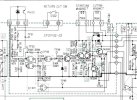
In thinking about the only portion of the NAND gate IC501 (Gate 4) to serve a logic function in the Sensor Board I tried to determine the conditions as to why the original designer wanted two valid inputs before the end-of-record function was activated. The dilemma in my thought process was that the two signals which were NAND were both the result of the Optical Sensor output. The only difference between them was how they were processed and what the resulting signals looked like. When I looked at the two signals on my scope at pins 12 and 13 both were present at the same starting time but the one on pin 12 was very short.
I did a test by pulling pin 12 HIGH and seeing if the desired output was generated at pin 11 (which it did) led me to believe that there may be no valid condition that would require both signals to be present and TRUE to generate the end-of-record function. After pulling up Pin 12 with a 12k resistor to the +12v rail assembled the table and tested all of the functions that are impacted by the activation of the Cuting Magnet circuit. The results are they all worked as they should. I am at the point where this may be the mod to the circuit that fixes my problem; it is not as elegant as finding the real problem and fixing what the original designers had in mind but it works. An additional benefit is that the circuit appears to be much easier to adjust without having both inputs to Gate 4 TRUE. It should be noted that the same result can be achieved by also changing Gate 4 to perform the Inverter function of the other 3 gates
In thinking about the only portion of the NAND gate IC501 (Gate 4) to serve a logic function in the Sensor Board I tried to determine the conditions as to why the original designer wanted two valid inputs before the end-of-record function was activated. The dilemma in my thought process was that the two signals which were NAND were both the result of the Optical Sensor output. The only difference between them was how they were processed and what the resulting signals looked like. When I looked at the two signals on my scope at pins 12 and 13 both were present at the same starting time but the one on pin 12 was very short.
I did a test by pulling pin 12 HIGH and seeing if the desired output was generated at pin 11 (which it did) led me to believe that there may be no valid condition that would require both signals to be present and TRUE to generate the end-of-record function. After pulling up Pin 12 with a 12k resistor to the +12v rail assembled the table and tested all of the functions that are impacted by the activation of the Cuting Magnet circuit. The results are they all worked as they should. I am at the point where this may be the mod to the circuit that fixes my problem; it is not as elegant as finding the real problem and fixing what the original designers had in mind but it works. An additional benefit is that the circuit appears to be much easier to adjust without having both inputs to Gate 4 TRUE. It should be noted that the same result can be achieved by also changing Gate 4 to perform the Inverter function of the other 3 gates