• The move to the new server is done. There are some software and database maintenance updates in process. This has us passing the hat around to help out. We appreciate any donations. Seriously, even a dollar helps. The payment page may be found here - https://www.audiokarma.org/support.html

Technics SA-160 repair advise

JayPare

Active Member
Hi all,

I in the process of bringing back to life a Technics SA-160 I found at the thrift store for 5$. I'm repairing it for my personnal knowledge, so I'm thinking of selling it and give the profit as a donation to the website.

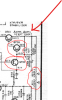
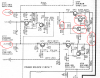
Right now it's not powering on. I opened it and noticed the voltage at B+ and B- are not correct. After a visual inspection, I found Q703, Q704, R771, R772 and R703 appear to be burned.
upload_2020-7-22_10-5-46.png

My question is, should I check any other part before ordering those? Any other advice?

The schematics can be found here:
https://www.hifiengine.com/manual_library/technics/sa-160.shtml

I will also create another thread for substitution for Q703 (2SC1685) and Q704 (2SC828) and link it here since those transistors seem to be hard to source except if you go with chinesse parts. However, I've read some reviews about them being fake so I don't want to take the risk of getting junk parts.

TIA
 
Register to hide this ad
Annotation 2020-07-22 100314.png

You say that R771 & R772 appear burned . Use the power law (P = I²R) to determine how much current would be required to max out these resistors at 1/2W each. 99% of that current also flows through R773 & R775. When R771 & R772 are dissipating 1/2W each what are R773 & R775 dissipating? What does that suggest?
 
View attachment 1932888

You say that R771 & R772 appear burned . Use the power law (P = I²R) to determine how much current would be required to max out these resistors at 1/2W each. 99% of that current also flows through R773 & R775. When R771 & R772 are dissipating 1/2W each what are R773 & R775 dissipating? What does that suggest?
I'm not sure what those resistor value are. Schematics tells 22 and 2.2 but 22 ohms doesn't really make sense to me, does it?

I have some picture of the actual resistor but it's really hard to read the band on themselve:
uiPwlZ_3N2Zloi_6BIPVt72ncx8bHxo2TNtNRVn27VIfmo4gY57KRSdn5baKADdUMGWTPHUTVaxA4VgTMqOrNyIpdd6anPBRZNIZS91fD2qlqGfRk9UBs2dhJAQzzzhpy-ePC9wmfaM7vW0waQp5sDvMZmBKVWL-hTH8tUJcrDcnzCaqSmmORXdeFaQn3AxuInLUoaNmtYLMYoKo9XI9tfb7H5xdEBXvY6WLPg9DshSaEtDaZXWZ62C5E1lExUyeQWEaxHBy1HXcQVLmGXFhhuwIZAPR1nTjV0G5A97WOhX2Ch5srXnrYV7duIOk0kqUF6a9RdJDSgxFSZ5HwYuK5VThZTxVCJ50RpQgo0soAjFG0Eyvv7pojk01K2wLX1bBs4kk-ocgxr7o5YaAPTI_JCHeLusxEEbrFx4hXTtc9l8QIBVaLCOarkr0eZ6cV8Ui0XGauVCXuMe2igVaQsNDMSMB_M3mo2oFcyfirZW9m2JQWFaewMeoAR3nBCktLPO7-wXWKoZWG1VeJIgODheUjq_t8gYcsAG8srVEPWxLMbiIVOPNJL7ZMwrt3QaHix8Tvz5CJ83zNt9pL59PsvsQT8ULp8NzWi-bbsptqORyEePVDXAgeaRMK6PwqERTnD4UaKyiaY8uK4fLYaxp_R1UBPxY0l4YuKGnKBPzMFPer4Tt0El4ofuPvjkftjG2cgM=w1250-h937-no


dL7qBE_svMbDrj3VxYuYL9yogJ7_BEWe-AUQmBuSVpf3hzYgUNMVhduEOxeaJ8Mw4NU7tg8Il9H4lOyxnhDnNa9nCLfDZzXmVFYd4m5cUHMh7kFQrPeAdtiDPAKpzw5tqu5peE9H51PKK-_7_kIy-JOu1rNebD5QRAaBmCtMNvj30nCFxhVQmtT9GAueXlZcrF7CDQwkHS8CceUGNOaudFlzRdavFcLiRHoXJjxJQA_jbLAYkiGonlfknJOVkW-Ta_nSKp_CnqQYlXLvAHwPXHLjrP2a-QEX-wZch_34S984bD6-XViCaKn7aYyO1927088w-gwv0pbkLTpuIDgugpEnllZlUD1ix5qV0HJJp-4FC-2sXcOZIgZL-2zA6wjj819a0jfgl-FgzkfhLD2N0prHrPtsWePxLyCLcgJ1MfYG-GmTvkfOHVrPRSpeIDbH7QpyCAT-O8wxQPwi2ZI8vsJ83HiPktnXbvdhqwiGuo7r1TzKUwXEYi7DKtcL4sMvb4qMbSJTOeeqpLP_01GKyJr0y51EFFhbKX0-DwEXsN2cwrrULrkIS7VaANhGXvIzeqNa1sEvkAl6rcjJp-ns8a4rdmdYat5g1ckClHOEdk2cmgeNCp09KwGJUtR0D8S8P8kM76nbVfaEvpR7GYfXq7KppE6Zru21arvgKys67N8FPFPG3yeN-Y36c-BcxoQ=w1250-h937-no


However, even without those value, to reply to your question, it suggests me that R773 & R775 are also burnt. And I guess it doesn't stop there?

TIA
 
Those are normal in sets of this era 22ohm and 2.2ohm

make sure all joints on power supply (parts with number in 700 range) like transistors and diodes and resistors... the regulator resistors (on heatsink next to power ic) often get dry joints... dry joints in regulated supply area can result in overvoltage which will result in the 24 ohm array to fold

15V rails are critical... not much will work without them
 
I appearantly misread the schematic and saw both of these resistors as 2.2 ohms. Doesn't change my comment though.

But why would they use 22 ohm 1/2W + 2.2 ohm 1/2W? Makes no sense in dissipation distribution. The 22 ohm resistor is always going to dissipate much more than that 2.2 ohm, yet they are the same wattage. again makes no sense. Why not use two 12 ohm 1/2W resistors? Are they really using that 22 ohm as a fuse?
 
Those are normal in sets of this era 22ohm and 2.2ohm

make sure all joints on power supply (parts with number in 700 range) like transistors and diodes and resistors... the regulator resistors (on heatsink next to power ic) often get dry joints... dry joints in regulated supply area can result in overvoltage which will result in the 24 ohm array to fold

15V rails are critical... not much will work without them
Thank you, I will.

Therefore @Ylli :
0.5 = 24.2 * I²

√(0.5/24.2) = I

I = 0.143 A

Are my math good? o_O
 
I read the schematic as two 2.2 ohm resistors, so for each resistor:
0.5 = 2.2I²
I² = 0.227
I = 0.477 amps.

At that current, for example R773 (4.7 ohm, 1/4W) would be dissipating:
P = I²R
P = 0.477² * 4.7
P = 1.07 watts

If that is actually a 22 ohm + 2.2 ohm then the 22 ohm would indeed dissipate the majority of the power.
 
The schematic I just pulled from hfe has them both as 2.2R / 1/2W if you expand the image enough.
You are right I think I sort of see a point between those two 2. Thanks for pointing this to me! :D

So @Ylli is my assumption that R773 & R775 are also fried good?
 
Certainly worth checking.
Anything else further I should check? I guess if they are bad I will need to keep checking further and if not I could stop there? Will do all this tonight! Thanks agin for your help I wouldn't even imagine getting such help! I <3 AK!
 
If R771 & R772 are indeed burned open, that indicates there was high current draw though that path. Within that power supply section, I see three ways that a high current could have been drawn:
1. Q701, Q703. Q704 plus D705 are all shorted.
2. C705, Q704, and D705 are all shorted.
3. C708 shorted.
4. or C422 shorted

OK, 4 ways.

Alternately, something downstream is drawing too much current from that +15.1 volt line.


As it sits, what voltages do you see at the +15.1 volt, +5.4 volt, -15.2 volt, and -30.6 volt points?
 
If R771 & R772 are indeed burned open, that indicates there was high current draw though that path. Within that power supply section, I see three ways that a high current could have been drawn:
1. Q701, Q703. Q704 plus D705 are all shorted.
2. C705, Q704, and D705 are all shorted.
3. C708 shorted.
4. or C422 shorted

OK, 4 ways.

Alternately, something downstream is drawing too much current from that +15.1 volt line.


As it sits, what voltages do you see at the +15.1 volt, +5.4 volt, -15.2 volt, and -30.6 volt points?
Will work on this tonight and update you! Thank you!
 
Ok @Ylli, @Goldie99, @SVI2004A I made some progress.

First of all, as it sits, the following connector are disconnected:
  • Tuner (J201, J202)
  • Volume circuit (J501)
  • Graphic equalizer amp circuit (J901, J902, J903, J905)
I took the reading anyway for -15V, +15V and +5V:
  • -15V => +0.42V
  • +15V => 0V
  • +5V => 0.38V
Components wise, I took out R771 and R772. R771 is reading OPEN and R772 is reading 9.3 ohms (instead of 2.2 ohms).

Going further, everytthing seems alright: R773 reading 5.25 ohms and R775 reading 5.2 ohms. However, R773 is two big ass resistor in parallel:

TrTeT50MQvH5RUNgPMh9sIbYOymPJbpr2YgWfSsQawo8MQ3uNP3HzQCux6xcEderVTpIKhupMvJdBjJEFlIbfhj_uK6i8TBxnFUsSTb-7ViB1rTiAVA05CqRe6aPyaWjWg-6bduO4i9ZbBfWCRCLPhlmgifCMPi8y-WpK_xlGE0cAtKnd6D47cgo90Hf987-IYGtBBQ2x-amArYHbYMEW0OdWKGhanG-8l7oebL61Sie-jWd9P0Udw5SdK-x9nmuriroYMMWZyPPPJEF5g3yBjml-fYL14EpLX6zCRYjAfRl2aaQX8Yixi47QesHxQ-uTo0_cRMLE8jLN4UC4OUhlehBVU_1Etg1v1TqRs61Sb-e6zJAnFCLDedxnJqM4Z2e0TRaxe2DkiY4N6OrghFy97xjJdYEw2AtdNHkQ78Ha_a91OImYfWHdXMgT9FYnPBQLlkO2Ee5mgzAJq66U7IZPqLl5S59hluzq-eNUENMolpXdp1zqNvvvpkqwka9j3e9qVV1myfNkhyFo9gWkgcDe0U6UTksOglsyDykq0UVBTF7vgPwLSxR1QaoLsWdopFYZ4fs8CnHkCYqkYMtINg-F1G2pKYl7Pz95Md_FERK4k_eynNFP8vjszY91XAKtUfUneSte6bwv03ywLM_Y0ARbh5IY-Y1t5LH7pRDeFNHgpC_D472MlPkoth0ryS-5r0=w1344-h1008-no


I was expecting a 1/4 watts, 4.7 ohms resistor, but if my math are right, this has an equivalent resistance of 5 ohms (this is fine) but 20 watts. Maybe it has been replaced in the past?

As far as R703, it reads 2.74k ohms so the burnt on it might just come from the transistor (Q704, 2SC828) sitting just beside it.

So what's next? Anything else I should test?

TIA
 
Last edited:
Looks like you got most of the loads disconnected from the Power supply. Since you have some burned parts on the positive side, let's start there. Remove the burned R771 & R772. You will eventually need to replace these with new 2.2 ohm 1/2 watt resistors, so add 2 or more of them to your shopping list. That 10 ohm 20W resistor resistor pair has got to go, so add a couple 4.7 ohm 1/4W and a couple 4.7 ohm 1/2 W resistors to the list.

Do you know how to test transistors and diodes with your DMM on the diode range? You probably will want to remove from the circuit and test Q701, Q703, and Q704. Also test D705 - you can't test it for Zener voltage, but it still should test as a standard diode.

Negative side. Do R777 & R778 appear OK? Better measure them with your ohmmeter - in circuit should be OK here. Then pull and test Q708, Q709, and Q710. Also diodes D709, D710, and D711. While Q710 is out of the circuit, test resistors R779 and R781. Add any bad parts you find to your shopping list.

Let's power it up and measure the voltage at the cathodes of D701 & D703 (same point). With the speaker switch in the 8 ohm position, it should be 35 volts or so. Then measure the voltage at the anode of D781. Should be -35 volts or so.

Do you have a dim bulb tester (DBT)? If not, you will want to assemble one. It can be as simple as a short extension cord with one of the wires cut and a lamp socket added in series. From now on, whenever we power up the receiver, we will want it connected to the power line through the DBT. Start with a 60W *incandescent* bulb for now. We don't want to burn out any new parts we install.

Advise your findings.
 
Looks like you got most of the loads disconnected from the Power supply. Since you have some burned parts on the positive side, let's start there. Remove the burned R771 & R772. You will eventually need to replace these with new 2.2 ohm 1/2 watt resistors, so add 2 or more of them to your shopping list. That 10 ohm 20W resistor resistor pair has got to go, so add a couple 4.7 ohm 1/4W and a couple 4.7 ohm 1/2 W resistors to the list.

Do you know how to test transistors and diodes with your DMM on the diode range? You probably will want to remove from the circuit and test Q701, Q703, and Q704. Also test D705 - you can't test it for Zener voltage, but it still should test as a standard diode.

Negative side. Do R777 & R778 appear OK? Better measure them with your ohmmeter - in circuit should be OK here. Then pull and test Q708, Q709, and Q710. Also diodes D709, D710, and D711. While Q710 is out of the circuit, test resistors R779 and R781. Add any bad parts you find to your shopping list.

Let's power it up and measure the voltage at the cathodes of D701 & D703 (same point). With the speaker switch in the 8 ohm position, it should be 35 volts or so. Then measure the voltage at the anode of D781. Should be -35 volts or so.

Do you have a dim bulb tester (DBT)? If not, you will want to assemble one. It can be as simple as a short extension cord with one of the wires cut and a lamp socket added in series. From now on, whenever we power up the receiver, we will want it connected to the power line through the DBT. Start with a 60W *incandescent* bulb for now. We don't want to burn out any new parts we install.

Advise your findings.
This reply is insane. I do have a DBT. Will do all this soon but in the mean time, for my personnal knowledge, is my assumption that the 2 10W 10 ohms resistor are not from factory good? Why would someone add this instead of 1/4W resistor?
 
Why insane? None of the outputs from this section of the power supply are correct, and there are some burned parts. Any/all of the parts I mentioned could be bad, and replacing some of the parts and leaving other bad parts still in the circuit could result in those new parts frying again. Better to check them all the first time through. As for the 2 10W resistors.... The schematic indicates a 1/4 W resistor, and a 4.7 ohm 1/4W resistor will handle 200 mA or so. Should be sufficient. It does look like they are using that resistor as a safety fuse in the circuit, so replacing with the proper part is a safety related repair. 'I' might put a 1/2W resistor there, but I won't tell anyone else to do so.

Why are they there? Might be all the previous 'tech' had, or the original 4.7 ohm may have failed because something downstream is drawing too much current, and rather than fix downstream a high wattage resistor was used - kind of like wrapping a fuse in aluminum foil because the specified part keeps blowing.
 
Back
Top Bottom