• The move to the new server is done. There are some software and database maintenance updates in process. This has us passing the hat around to help out. We appreciate any donations. Seriously, even a dollar helps. The payment page may be found here - https://www.audiokarma.org/support.html

Technics SA-300: Let the smoke out

b10alia

New Member
Hoo boy.

I was in a bad mood this afternoon and figured a nice 8 track would help. Plugged in the power strip that all my gear is plugged into (I never leave it plugged in unless I'm using it) and I get a loud hum from the speakers. Was messing around with the selector knob, volume, etc., to see if anything affected it. The only thing that made any change was turning off the speakers-- volume at zero and I was still getting the hum. Then I noticed a wisp of smoke coming out of the top of the receiver.

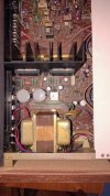
I pulled it out and took the top off, expecting a blown cap, but there's nothing obviously wrong inside:
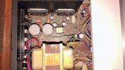
IMG_20260916_194938880_AE.jpg

IMG_20260916_195000252_AE.jpg

I don't even know where to start with troubleshooting. Based on where the smoke came from, I'd guess that one of the amp chips might have gone, but that's all I've got. I can solder and I have the service manual, but that's about it, I've never tried to repair anything electronic at this level. I'm not really interested in anything modern, I like the woodgrain silverface look with mechanical buttons, and I like the idea of playing music from something that was new when the music was new.

I think I need to learn unless I want to pay through the nose for a known good known serviced vintage amp. Give a man a fish or teach a man to fish, I'd rather know how to fish, even if I'm not ever going to be the best in the world at it.

Any ideas where to start? Are there known common issues with these particular receivers beyond caps?
 
Register to hide this ad
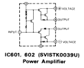
I looked at the amp chips, you can get a very similar part number on ebay but it doesn't match the service manual exactly- there was a thread about this but now I can't find it. It suggested there was some electrical difference in the circuit. The ebay ones I was looking at were i.e. these ones vs the service manual SVISTK0039U.

Supports burning resistors may go with bad amp chips:
https://audiokarma.org/forums/threads/vintage-technics-receiver-blown-smoking.545709/ (last post)

https://audiokarma.org/forums/threads/technics-sa300.47099/ (second post)

How would I determine the amp chips are bad or good? I don't really want to plug it back in with the smoking, so I'd be looking more at pulling them. I can borrow a decent multimeter from work, I have a junky one. And do these just fail or is there something else in the circuit that kills them?

(back up a second)-- how can I narrow down where the problem is, if it's not actually the amp chips? The parts shotgun has hurt me many times before.
 
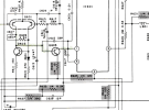
If I read it right the resistor is R625 which is the first resistor on the main voltage rail, maybe check Q605 but my money is on the left STK being bad.

Screenshot 2026-09-17 145111.png
 
If I read it right the resistor is R625 which is the first resistor on the main voltage rail, maybe check Q605 but my money is on the left STK being bad.
It is R625, and the hum was mainly coming from the left channel.


I was able to find the thread I mentioned: https://audiokarma.org/forums/threads/replace-stks-with-rcs16s-design-technics-sa-300.854831/

The OP said he initially used STK0039 packs from eBay. There was some concern about the DC offset being too high, and then it sounds like he replaced the packs with rcs16's module kits from eBay and still had a high offset, then recapped it and changed a zener diode and some transistors, and that fixed it. He only dropped 20-80 mV out of 400 by using the rcs16 STK0050 kits, but about 300 mV by changing the other stuff.

I don't fully understand what was being said in this thread. I know what a zener diode and a transistor are and how I would test them, but only out of circuit. DC offset I'm assuming is the voltage you'd measure across the speaker terminals, but with nothing playing? and at max volume?

The ICs are a lot more intimidating. It seemed like the generic packs worked for the OP, but it seems like he had problems elsewhere. The cap on pin 5 was noted as probably not an issue, but I don't know what this means (quotes from the linked thread):
For reference. (from SA-300 SM) My 2 cents - the cap is probably to improve stability of the Quasi complimentary circuit, and the full complimentary circuit shouldn't need it.
Personally I think it would still work, the biasing voltages look much the same, and that cap provides a bit of negative feedback for high freq stabilization.
Do the generic SK0039's have a difference from the original STK0039U's that makes this cap unnecessary? Should the cap be removed and jumped out if a generic pack is used?

I'm assuming that the left IC is shorted, but I don't know how I would test that. I had thought these were socketed for some reason but they are definitely soldered in on mine. This removes a lot of the argument for the generic packs. It doesn't look like a bad soldering job at all either way. If I can figure out that the ICs are the problem, I'm probably going to go with the rcs16 kit as replacements. But I don't know how to test the packs, or how to investigate anything else, given I don't really want to plug it in again at the moment. I can borrow a variac from work but I don't know what I would do with it, I've just seen it mentioned skimming through stuff.
 
I have to unsolder the ICs to remove them. How would I test them out of circuit? If I'm taking them out to swap them around, I've already got them out. If the problem isn't with them and it's somewhere else (which seems unlikely), I don't have to build a circuit board or decide if I want to roll the dice with a generic pack.

1789775174697.png

Looking at that, I would GUESS I should have on diode check mode on the meter:
Pin 0 +: some voltage 1, 6, 9; none on 2, 3, 5
Pin 0 -: some voltage 1, 2, 3, 5; none on 6, 9
Pin 1 +: some voltage 0, 6, 9; none to 2, 3, 5
Pin 1 -: some voltage 0, 2, 3, 5; none on 6, 9
Pin 2 +: some voltage to all pins except 3, none on 3
Pin 2 -: some voltage to 5 only, none anywhere else
Pin 3 +: some voltage to all pins except 2 and 5, none on 2 and 5
Pin 3 -: reversed from above
Pin 6 +: some voltage to 9 but none anywhere else
Pin 6 -: reversed from above
Pin 9 +: no voltage to any other pin
Pin 9 -: some voltage to every other pin

This is the best I can make of it but it doesn't seem right. There's going to be something to "some voltage" (forward drop?) as well, but I don't know what would be good and what would be bad in terms of readings.

Can you even test a pack like this with a regular multimeter? Diode check isn't 36V.

Dim bulb: I will make one because it seems useful, but I don't think it would help much with this other than "there is a problem". Unless you can't test the packs with a multimeter, in which case swapping them around makes more sense
 
Last edited:
img_20260916_195000252_ae-jpg.3838031

You might want to think about replacing those two main caps (big gray ones). They look like they are OEM and may be bulging slightly at the top.

:idea:
 
You might want to think about replacing those two main caps (big gray ones). They look like they are OEM and may be bulging slightly at the top.

:idea:
The caps are upstream of the resistor and yes, I want to replace them. But I don't see how this would cause R625 to burn up. I'm not saying you're wrong, I'm saying that I don't understand enough about this to connect the symptoms to the issue.
 
The caps are upstream of the resistor and yes, I want to replace them. But I don't see how this would cause R625 to burn up. I'm not saying you're wrong, I'm saying that I don't understand enough about this to connect the symptoms to the issue.
The capacitors have plastic disks on the top, as the plastic wrap shrinks over the years they bulge up. You can press on the top to verify or just cut them off.
 
Last edited:
That's interesting, I had assumed they were metal. But it sounds like it's not something to worry about.

I am planning on recapping this, I ordered a cheap soldering stations/desoldering gun to do the STKs and access from the bottom is very good. This is not to solve a problem, it's for long term reliability, so it's not my topmost priority unless I can verify that one or more caps is actually bad.

It seems more likely that the issue is with one of the packs, like milo63 originally suggested, but I still don't know how to test them. I have to unsolder them to swap them anyway.

I'd way rather test them out of circuit if possible. It would verify that "yes that's the problem" and would mean that, if there is something wrong elsewhere on one channel, it wouldn't kill the other pack. If I can test them and they're good or at least within spec, then I need to look elsewhere.
 
Back
Top Bottom