• The move to the new server is done. There are some software and database maintenance updates in process. This has us passing the hat around to help out. We appreciate any donations. Seriously, even a dollar helps. The payment page may be found here - https://www.audiokarma.org/support.html

Technics SA-500 No FM - 2SC1047 voltages

Anaxas

New Member
Hi,

On my Technics SA-500 the FM suddenly went 'mostly' out .. but quite faint when the muting is off, and silent when the muting is on. AM never worked for the couple of years that I owned it.

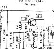
While trying to find the issue I measured the transistors and Q2 ( 2SC1047 ) has an emitter voltage of 1.0 Volts , but in the service manual it should be 11.1 V . The base measures 1.7 and the collector measured 11.7 (11.2 in the manual) . I pulled the 2SC1047 from the board and it still tests as an BJT-NPN transistor (hFE 85) which at rank D is low (there is a D on the chip) , which should be 100 - 260.

I re-capped the tuner board to eliminate the rest of the green crusty legged capacitors (power side was done years ago) and replaced the equally messy VR101 and VR102. As somewhat expected , this did not solve anything, but there were several capacitors way out of spec.

I'm tempted to replace the 2SC1047 since it's reading so low on the emitter, but technically I'm out of my league on analyzing the circuit. Could there be anything else that would cause the voltage there to be so low?

Any help would be appreciated.
 

Attachments

  • Q2.JPG
    Q2.JPG
    253.5 KB · Views: 20
Register to hide this ad
it appears to be working ok .. you need to find out why the base voltage is low . it needs to be about 600 mv higher than the emitter .
have a play around with this .. https://www.falstad.com/circuit/e-npn.html
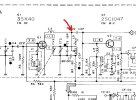
that looks wrong in the pic .. decimal point is wrong place . should be like 1.11 v at emotter .
guess the problem isnt this bit .
 
Last edited:
Thanks for the lead .. I will look into this. I have a working SA-600 with an identical virgin tuner board to inspect - so if it's a misprint in both service guides I will report back.
 
this is from sa-200 a bit different but close enough . i did check sa-600 schem but that's same as 500 one .
 

Attachments

  • Screenshot from 2023-11-20 18-17-50.png
    Screenshot from 2023-11-20 18-17-50.png
    44.4 KB · Views: 12
Thank you @petehall347 - You are correct that there is a misprint for Q2 in the service manual - I measured against the working and very similar SA-600 and the emitter voltage is just over 1V for the 2SC1047
C: 11.6
B: 1.7
E: 1.03

Onwards down the path to find the real problem.
 
If you can get at this point, connect your voltmeter's red lead to this point. Leave the black lead unconnected. (You are using the meter lead as an antenna). Does FM come in any better?

Screenshot 2023-11-22 100810.jpg
 
Thank you @Ylli , I'll give that a look, but I'm doubtful that's the issue. I took measurements of all the transistors - It appears that AN377 is having issues with it's voltages

PIN : Expected : Measured
1 : 2.1V : 2.1V
2 : 2.1V : 2.1V
3 : 2.1V : 2.1V
4 : 0V : 0V
5 : 1.5V : 5.1V
6 : 5.7V : 9.0V
7 : 5.7V : 9.5V
8 : 5.6V : 8.5V
9 : 5.6V : 8.9V
10 : 5.6V : 8.9V
11 : 11.2V : 10.4V
12 : 3.2V : 2.8V
13 : 0.9V : 0.64V
14/15/16 : 0V : 0V

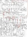
Pins 5 through 10 have about 4V extra on top of the expected values .. Looking at the schematic solely at what's connected to PIN 5 on the AN377 , it should only be fed a voltage similar to what's on the collector of Q305 (0.8V expected / 0.97V measured) going through a couple of resistors on either side of the diode D103.

Since Vcc on Pin 11 (AN377) is close to what's expected and all other transistors measure correctly - I would guess that it's a problem with the AN377 failing internally since I can't see anything external to that chip a relation between all those pins.
 
I again measured the 8/9/10 pins multiple times and the voltages were 8.69, 8.74, 8.69 .. they were drifting slightly upwards during the first few minutes powered on, but stabilized at those values. I may have made a mistake recording the values the first time or started measuring from pin 8 and down each side of the chip and it drifted up by the time I did the 9-16 pins .
 
Pins 8, 9, and 10 are connected together through coils. I would expect the voltage on all three to be the same (or very close), Earlier, you had 8 & 9 0.4 volts apart so I was wondering about L101. The 0.05 difference you see now I can chalk up to measurement variations.

What voltage do you see at IC101 (AN377) pin 13, both when receiving a strong signal and between stations?
 
So it seems like it is working, but it is not getting enough signal to fully unmute it. Pointing to the front end, Q1, Q2, IC201.
 
(Edit: pin 12 is also a mute output. What voltage do you see on that pin with a strong signal and between stations?)


Pin 13 of the AN377 (IC101) is the meter drive output. The voltage on this pins should be dependent on the signal level into the chip. If I decoded the data sheet properly, the voltage on that pin should be near zero for no signal, and up to almost 5 volts with a strong signal. When the voltage on pin 13 (along with the adjustment of the Muting Level pot) is too low to turn on Q101, Q101 collector will go high. That high is applied to the non-inverting Schmitt trigger consisting of Q102 & Q103. The high output of Q103 passes through S4 and is applied to the emitter of Q305. Driving the emitter of Q305 high will cause Q303 and Q304 to be turned on, muting any audio coming out of the MPX chip (IC301). The high on the collector of Q103 also passes through D103 and R106 to pin 5 of the AN377 (IC101). A high on pin 5 mutes the audio output of that chip.

The 0.82 volts you see on pin 13 with a strong signal is barely sufficient to turn on Q101, even with the muting pot set to the top. So either IC101 itself is defective, or it is not receiving sufficient signal on it's input (pin 1). If IC101 is not receiving sufficient signal, that points to Q1, Q2, IC201 and associated circuitry. (If you have the meter pot set to zero resistance, it is *possible* it could load down the output at pin 13. Be sure that pot is somewhere mid-range for now)

I can not find a source of the AN733 but there is an NTE replacement - the NTE788. That should be readily available.
Screenshot 2023-11-25 160120.jpg
 
Thank you @Ylli . I checked pin 12 and it's was 2.46V regardless if on or off station. I have ordered an IC201 (AN217) and a couple different replacements for the AN377 (ECG788 / HA1137W ). I'll update after they arrive
 
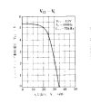
Here is the data sheet graph of Pin 12 voltage vs signal strength. 2.46 volts seems to be halfway between mute and don't mute.
Screenshot 2023-11-26 103324.jpg
 
Success! I replaced IC101 (AN377) chip with an inexpensive eBay "FM IF SYSTEMS IC T2T-1 (ECG788/CA3089E)" chip and it's fixed. It also corrected the tuning needle offset issue and best of all I didn't have adjust anything (mute level, signal meter, separation, etc). I previously replaced IC201 (AN217) with an exact original, but it made no difference (and my AM is still not working, but that's much less important). Thank you @Ylli and @petehall347 for your input and guidance.

Summary:
Issue: FM stopped working and was very very faint when muting was off. Previously, tuning needle would not exactly center.
Found Symptoms: IC101 ( AN377 ) Pins 5-10 had about 3.5V extra voltage on them.
Fixed with: Replacement of IC101 with T2T-1 (ECG788/CA3089E) chip.
Also performed (but made no difference): Recap of the tuner board, Replacement of IC201 (AN217), Replacement of 2 Variable resistors
 
Congratulations on the FM fix! You replaced IC201 and AM is still not working? IC201 pretty much is the whole AM system.
When set to AM, you should have about 5.8 v @ pin 4, and 7.8 volts @ pins 9, 12, and 15.
 
Nice Anaxas.
I had the exact same issue with my Technics SA-500 and replaced the chip that you diagnosed. My FM source has been totally restored. I did have to tweak the alignment settings but I had messed with them earlier trying to diagnose the problem. To summarize the fix, I will repeat your summary:

Issue: FM stopped working and was very very faint when muting was off. Previously, tuning needle would not exactly center.
Found Symptoms: IC101 ( AN377 ) Pins 5-10 had about 3.5V extra voltage on them.
Fixed with: Replacement of IC101 with T2T-1 (ECG788/CA3089E) chip.

Cheers!
 
Back
Top Bottom