

SebastianH
Member
Hey all,
I recently concluded my restoration project of a Technics SE-9600 - part 1 anyway.
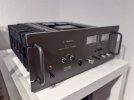
I got this amp (and the SU-9600/ST-9600) a couple of month back. I enjoyed the design and built-quality of the amplifier and everything seemed to be original including original outputs. A couple of slightly dirty switches, pots, but those were actually not that bad at all. A closer inspection showed one carbon film resistor had its case cracked open, exposing the helical carbon film, but even this resistor measured fine. The caps were mostly still usable (spot check only), but after almost 50 years one has to expect some degradation. Of course this amp too has a certain amount of the dreaded glue. Otherwise it worked just fine. Except for the smell of those cheap phenolic resin boards, especially when the amp heated up. So what was planned as a simple service got a bit out of hand: I decided to design new PCBs - a total of four:
My plan was to not re-use any component of the old boards and keep those ready to revert this amp to its original state if I'm ever inclined to do so. This also meant completely new semicondutors that can be bought new from Mouser or Digikey.
I tried to keep the design as close as possible to the orginal with some minor exceptions mostly for stability. For example:
The old Power Source Circuit Board:
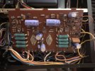
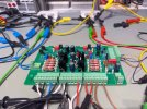
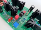
The new board while bench testing:
The old Driver Circuit Board:
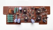
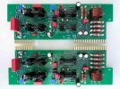
The new boards:
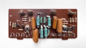
The old Meter Circuit Board:
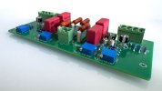
The new Meter Circuit Board:

Testing the new boards:

I measured ca. 0.03% THD @1kHz, 110W into 8 Ohm; ~0.007% THD @ 1kHz, 10W into Ohm. It is not not the best performing amplifier in the world and the modification most likely did not improve the performance either, but it works great and is built like a tank (and the smell is gone). For a couple of weeks I've been using the amp as my main amp daily and for hours and I honestly enjoy it a lot.
Have not yet finalized the design of the last board (SUPA2620 Meter Range Selector Board) and I think I will only design this board if one of the lights burns out and I have to take of the front panel off anyway. Also, to the horror of some poeple I haven't renewed the thermal interface of the outputs yet; all this remains for the second part of the restoration down the road. Btw.: the amp idles at 10mA (5mV across ~0.5 Ohm per emitter resistor), or 0.5W per output transistor which is pretty much nothing. No surprise that the heat sinks remain cold to the touch, both idling and with my usual very moderate listening levels in the <1W average range. Total power consumption idle is 28W, and <=35W average (subjectively normal volume)/<=50W average (loud).
Note: I don't do circuit/amp design professionally. I found it a bit difficult to get this amp stable across different operating conditions. LTspice can help a bit to get some insight, but ultimately it's a bit try and error. For the most part I think I succeeded, but I'm not able (and willing) to test this amp like one has to do for a commercial product. I found an interesting result while doing a frequency sweep at 110W into 8 Ohms where my QA403 showed some "ripple" in the frequency response curve at around 50 to 400 Hz that disappeared at 100..105 or so W. I did not track down the reason for this - possibly power supply related, but I can't rule out some stability issue either, could possibly even be related to my currently slightlyjanky test setup For now I also don't intend to track it down, just because I will never come anywhere close to even 20W/channel except during those kind of tests.
More details about this project can be found on my personal website: https://sebastianharnisch.de.
If there is any interest in this project, I'm happy to answer questions and go into more detail of certain aspects.
- Sebastian
I recently concluded my restoration project of a Technics SE-9600 - part 1 anyway.
I got this amp (and the SU-9600/ST-9600) a couple of month back. I enjoyed the design and built-quality of the amplifier and everything seemed to be original including original outputs. A couple of slightly dirty switches, pots, but those were actually not that bad at all. A closer inspection showed one carbon film resistor had its case cracked open, exposing the helical carbon film, but even this resistor measured fine. The caps were mostly still usable (spot check only), but after almost 50 years one has to expect some degradation. Of course this amp too has a certain amount of the dreaded glue. Otherwise it worked just fine. Except for the smell of those cheap phenolic resin boards, especially when the amp heated up. So what was planned as a simple service got a bit out of hand: I decided to design new PCBs - a total of four:
- SUPA2580: Power Source Circuit Board
- SUPA2590 and SUPA2600: Driver Circuit Boards, Left/Right Channel
- SUPA2610: Meter Circuit Board
My plan was to not re-use any component of the old boards and keep those ready to revert this amp to its original state if I'm ever inclined to do so. This also meant completely new semicondutors that can be bought new from Mouser or Digikey.
I tried to keep the design as close as possible to the orginal with some minor exceptions mostly for stability. For example:
- I eliminated a part of the resistor/capacitor network in the feedback circuit for the lower than normal damping factors by isolating one pin on each of the Driver Circuit Board with Kapton tape, because - as I found out - this significantly decreased amplifier stability with the new silicon. I didn't care enough either to figure out how to change the feedback network to increase stability while fully retaining this function. Now this function is not fully disabled, but its effect is reduced. And I couldn't care much less. (If you're not familar with the SE-9600: It has the "feature" of a selectable damping factor. In my opinion Technics never should have implemented this "feature": Result using the lower damping factor settings is a flat and mushy sound. I'm not sure why I would ever want to make my amp sounding this bad intentionally.)
- Some other changes for stability, i. e. adding and/or changing R/C's.
- Fiducial marks on the PCBs
- many resistors/diodes are raised from the board (even signal diodes for whatever reason). All transistor/diode legs (except for the large TO-220 transistors) and many power resistors use either ceramic spacers or clear heat shrink and so on.
- Debug LEDs, high efficiency, ca. 100µA each. The LEDs on the driver board light ab at ~>+-42V. On the Power Source board there are LEDs for the unregulated supply (cc source; >+-2V) as a warning indicator and on the regulated supply. Were really handy while testing
- Use of pluggable screw terminals for easier testing/servicing
The old Power Source Circuit Board:
The new board while bench testing:
The old Driver Circuit Board:
The new boards:
The old Meter Circuit Board:
The new Meter Circuit Board:
Testing the new boards:
I measured ca. 0.03% THD @1kHz, 110W into 8 Ohm; ~0.007% THD @ 1kHz, 10W into Ohm. It is not not the best performing amplifier in the world and the modification most likely did not improve the performance either, but it works great and is built like a tank (and the smell is gone). For a couple of weeks I've been using the amp as my main amp daily and for hours and I honestly enjoy it a lot.
Have not yet finalized the design of the last board (SUPA2620 Meter Range Selector Board) and I think I will only design this board if one of the lights burns out and I have to take of the front panel off anyway. Also, to the horror of some poeple I haven't renewed the thermal interface of the outputs yet; all this remains for the second part of the restoration down the road. Btw.: the amp idles at 10mA (5mV across ~0.5 Ohm per emitter resistor), or 0.5W per output transistor which is pretty much nothing. No surprise that the heat sinks remain cold to the touch, both idling and with my usual very moderate listening levels in the <1W average range. Total power consumption idle is 28W, and <=35W average (subjectively normal volume)/<=50W average (loud).
Note: I don't do circuit/amp design professionally. I found it a bit difficult to get this amp stable across different operating conditions. LTspice can help a bit to get some insight, but ultimately it's a bit try and error. For the most part I think I succeeded, but I'm not able (and willing) to test this amp like one has to do for a commercial product. I found an interesting result while doing a frequency sweep at 110W into 8 Ohms where my QA403 showed some "ripple" in the frequency response curve at around 50 to 400 Hz that disappeared at 100..105 or so W. I did not track down the reason for this - possibly power supply related, but I can't rule out some stability issue either, could possibly even be related to my currently slightlyjanky test setup
For now I also don't intend to track it down, just because I will never come anywhere close to even 20W/channel except during those kind of tests.More details about this project can be found on my personal website: https://sebastianharnisch.de.
If there is any interest in this project, I'm happy to answer questions and go into more detail of certain aspects.
- Sebastian
Last edited:


