


Hollow_Man
New Member
Hello
I have a Technics SH-3434 audioscope that has a fault in the wave form
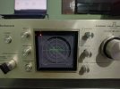
The horizontal line should cover the entire width of the screen but in my equipment it is compressed
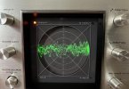
When I send a constant frequency the wave is compressed in parts and at the middle point it breaks
I thought the problem could be the Catode-Ray Tube but the image is seen in all the screen in 4 CH scope mode
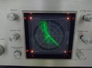
I don't have much knowledge in audioscopes but it seems that the problem would be in the High Voltage Circuit

According to the Technics SH-3433 audioscope manual (a similar model) the High Voltage Circuit has numbered points that indicate its functions (Focus, Brightness, Position, horizontal adjustment)
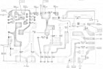
In the SH-3434 model the High Voltage Circuit has a variable resistor at the point where the horizontal adjustment is, unfortunately no matter how much I turn the VR the wave does not finish expanding
The variable resistor works, the electrolytic capacitors work, the voltage The transformer input voltage (green wires) is 440V, the same as indicated in the manual. I haven't been able to measure the voltage going to the CRT yet because my multimeter only reaches 1000V DC, and the output voltage is 1130V DC, according to the manual.


Another probable cause of the failure could be the power supply to the deflection yoke on the X axis (+X and -X), assuming X is the horizontal axis and Y is the vertical axis.
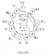
According to the manual, point ⑪ (X-) and point ⑫ (X+) on the back of the CRT would be the side deflectors in charge of stretching the image horizontally.
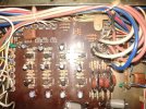
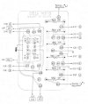
The orange cable (X+) and the gray cable (X-) connect to the Scope Driver Circuit Borad, in the SH-3433 manual the Rear Phase Switch is separate from the Scope Driver Circuit, but in the SH-3434 model I have this is integrated. It may be that some component of the Rear Phase Switch is the cause of a low energization of the deflection yoke.
Could you help me with this problem?
I would appreciate any comments that guide me on this.
Thanks.
I have a Technics SH-3434 audioscope that has a fault in the wave form
The horizontal line should cover the entire width of the screen but in my equipment it is compressed
When I send a constant frequency the wave is compressed in parts and at the middle point it breaks
I thought the problem could be the Catode-Ray Tube but the image is seen in all the screen in 4 CH scope mode
I don't have much knowledge in audioscopes but it seems that the problem would be in the High Voltage Circuit
According to the Technics SH-3433 audioscope manual (a similar model) the High Voltage Circuit has numbered points that indicate its functions (Focus, Brightness, Position, horizontal adjustment)
In the SH-3434 model the High Voltage Circuit has a variable resistor at the point where the horizontal adjustment is, unfortunately no matter how much I turn the VR the wave does not finish expanding
The variable resistor works, the electrolytic capacitors work, the voltage The transformer input voltage (green wires) is 440V, the same as indicated in the manual. I haven't been able to measure the voltage going to the CRT yet because my multimeter only reaches 1000V DC, and the output voltage is 1130V DC, according to the manual.
Another probable cause of the failure could be the power supply to the deflection yoke on the X axis (+X and -X), assuming X is the horizontal axis and Y is the vertical axis.
According to the manual, point ⑪ (X-) and point ⑫ (X+) on the back of the CRT would be the side deflectors in charge of stretching the image horizontally.
The orange cable (X+) and the gray cable (X-) connect to the Scope Driver Circuit Borad, in the SH-3433 manual the Rear Phase Switch is separate from the Scope Driver Circuit, but in the SH-3434 model I have this is integrated. It may be that some component of the Rear Phase Switch is the cause of a low energization of the deflection yoke.
Could you help me with this problem?
I would appreciate any comments that guide me on this.
Thanks.