• The move to the new server is done. There are some software and database maintenance updates in process. This has us passing the hat around to help out. We appreciate any donations. Seriously, even a dollar helps. The payment page may be found here - https://www.audiokarma.org/support.html

Technics st-c04 digital display not turning on

allanmatters

Active Member
I will begin by saying I shorted something in the board myself as I was trying to find a way to cool down the D880 transistor.

Let me explain: the tuner was working prior to this. The only issue with it was that it would run for an hour or so until the d880 transistor would get really hot. After that, it would auto tune on its own and shut down.. I'd have to wait for a couple of hours before I can listen to the FM again.

I checked all the resistors around it by pulling them off the board and measuring their values. All seemed good around that d880 transistor. I connected a mini heat sink to the d880 transistor, thinking that the heatsink would help to dissipate the excess heat and the tuner would supposedly run for longer. But the unit would still auto tune and shut down later after an hour of usage.

So I attempted to remove the d880 transistor and connect it to the main chassis with extended wires. I made sure of the "collector" "base" and "emmiter" terminals (as I know it's goes in the board in one way only) and I connected everything correctly. I then attached the d880 transistor to the main chassis and put some heatsink compound between the transistor and the chassis before screwing it up in place.

Switched it on and a small spark flashed (not sure where) and boom it was dead. The digital display did light up for those breif 2 seconds.

This was a cheap fix. But looks like I've done more damage. (I know, it's a really dumb move)

Things I checked
-fuse (good) (changed it anyway)
-all resistors around the D880 (good)
-replaced the d880 (even though the old one seemed good)

Checked the board for any signs of burnt resistors(also removed the ones around the d880 and checked (all good) . Every things seems fine by observation. What could possibly go wrong? The digital display does not come on now. Just the horizontal thin maroon lines in the digital display light up very dimly when it's powered on.

Finding it tough to get the service manual . Tried hifiengine and a couple of others. It's just not there. I've have yet to check the small 3 legged transistors. But there are quite some of them.

Appreciate any one's help here.
 

Attachments
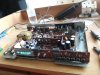
  • 20210911_134525.jpg
    20210911_134525.jpg
    125.1 KB · Views: 18
Last edited:
Register to hide this ad
Is the transistor one of those where the collector is electrically tied to the case? If so, and you screwed it into the chassis, everything ahead of it would be expected to go boom. If there was a resistor ahead of the transistor:

resistor.jpg


Resistance was futile. You have been assimilated.
 
Your problem initially was too much current draw through that transistor, not a cooling issue.

Very likely you had a bad capacitor turning into a resistor. You now have a blow power supply issue, and will have to track down and replace all the blown bits.

If you have the time you can draw up a schematic from the circuit board. I did this for a daisy wheel printer 30 years ago, and eventually tracked down a bad transistor to allow it to power up. Didn't fix it, as the real issue was a bad IC on the logic board, and it was 20 plus years old then. Still downstairs if I ever want to get crazy and fix it, but I'm pretty sure there are not computers around to drive it any more.

Digital tuners have a 5V supply to the CPU and tuning parts, and usually a 12V supply for the display (fluorescent) and oscillators. Chances are you blew up both of them and will have to track back to the rectifier and smoothing caps.

HiFiengine has the ST-c03 manual, but I don't see a D880 on it, is that the number on the transistor or the number on the board?

Stereomanuals.com has the manual, but getting one could be an issue, he's had CoVid and was quite ill, on top of being long retired. Shoot him an email and inquire.
 
Last edited:
Does that thing get any AM reception? It looks like the ferrite rod is mounted inside the metal chassis.
 
Lots of receivers of that era have internal AM ferrite rod antennas. Work pretty well for strong stations.
 
Right, the st-c03 does not have a d880 transistor. I did go through that manual as a walk through. But I don't think these tuners circuit boards are quite alike.

D880 is written on the transistor.
 
Last edited:
That is a 2SD880 transistor then, a voltage regulator most likely.

The circuits are probably similar, what is the number on the circuit board where that transistor was installed? Most likely a Q7xx or Q9xx, depending on where it is in the circuit.
 
Yes, it's a 2SD880. I put in a new one.

On the board, mentioned near the 2sd880 transistor is Q701.

On the board, the other mini three legged transistors around that area reads as Q702 (on the small 3 legged transistor it reads as C945 Q114a) and also a Q905.


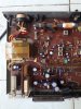
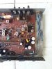
I have taken two separate pics of the unit so you can have a clear look at the board
 

Attachments

  • left.jpg
    left.jpg
    149.7 KB · Views: 11
  • right.jpg
    right.jpg
    147.2 KB · Views: 11
Last edited:
Here is a close up on where the other small transistors are located around the 2SD880

EDIT: I replaced C945 with C1815. Based on some research I did, it was said somewhere C1815 is an equivalent. No luck yet. Not sure if the collector, emitter and base is of the same arrangement on the C1815 though they both look alike.

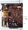
The Q905 is an A733 transistor (well this particular one is faded. Cant see the digits at all. The ends of the legs seem a little brown/rusted looking when viewing the transistor from the top).I took it off cleaned it up put it back on the board. My meter did show some readings when I tested it. I am able to identify the rest. There are quite many of them - Q906, Q907, Q908, Q909(all A733 transistors). They are also present near the "power on switch" assembly if you look closely on the image below Q707 and Q706 (A733 transistor)
 

Attachments

  • tranasistor location left side of board.jpg
    tranasistor location left side of board.jpg
    159.8 KB · Views: 8
Last edited:
When you say voltage regulator. What is it you are referring to? Diodes, IC's, rectifiers or transistors. Forgive me as I am not that technical.
 
Q701 is a power pass regulator transistor, probably has a capacitor and resistor network to the base (and ground) which, along with Q702, regulates the 11.9V supply for the tuner circuits. You need to get a component tester, one of the expensive ones will do fine. That will give you an idea of the gain and operational state of transistors and condition of capacitors.

I would replace the electrolytic capacitor on the base of Q701, and test Q702 (not replace). Verify that the zener diode and capacitor on the base of Q702 are good, if they got roasted by the short on the collector of Q701 when you stuck it on the chassis you won't get voltage to the tuner. Emitter of Q701 should be close to 12V.

Check the rectifier diodes too, very likely you popped one or two of them, and that will leave the unit dead. Should have 24V AC on one side of the rectifier and 24V DC on the collector of Q702. Not 24V power, no tuner.
 
Unit was powered up while I did the following tests.

Rectifier diode D704 10.61V AC
Rectifier diode D701 33.9V AC
Rectifier diode D703 0.024V AC
Rectifier diode D702 0 (nothing)

I measured only the positive side of the diodes by connecting the negative pin of the milti-meter to the chassis and the positive pin of the multi-meter to the + side of the black diodes

Not sure how to measure the zenor diodes

Collector of Q702 I got 5.2mV DC (this is the replacement transistor which I put in C1815) I will put back the original c945 tomorrow morning and try. Its late night here

I have not replaced the electrolytic capacitor on the base of Q701. However, I have a spare one with the exact value. That capacitor reads as 16v470uf)

However, do let me know what is the state of the diodes. And if they have been blown how would I get their value. Appreciate your help so far
 
Last edited:
Also not able to verify the number written on the zenor diode D706. It's faded. How to test a zenor diode with a multi-meter? Should I take it off the circuit board and test it? Or on the board is fine?
 
Probably need to find a correct service manual for the -04, the -03 is different. Probably quite similar, but laid out differently.

The power supply is not a standard "plus and minus x volts" since the tuner is only 12V and 5V, I'm assuming the output is cap coupled. I'm not sure the voltages on the -03 schematic are going to match all that well.

Probably need to pull one end of the diodes to check, too many ways to conduct around them. If you have a diode check function on your meter, they should read OL or open in one direction and 0.6 to 0.8 V in the other (voltage drop in forward mode). If you don't have a diode check function, they will conduct in one direction and not the other. The zener is the same, although probably not the same voltage drop. Can't test it for correct reverse voltage without a test circuit, but if it's fried it will ether be shorted and conduct both directions or be open in both.

I suspect you have blown at least one of the rectifiers, and as a result have no power in the tuner.
The
 
I took off all the rectifier diodes from the board D701 D702. D703 and D704. All of them read between 0.535v to 0.554v on the meter (in the diode mode option). When I interchange the pins I get OL on the meter (for all diodes). Yes my meter has a diode check option (attached a pic) . Are the diodes good?
Also, how would I get the value of the diode? There is nothing written on them. I put them all back into the board. They seem fine I guess.

Took out zenor diodes D922 and D706 from the board- tested them They showed 0.616v on one side and OL on reverse side. Put them back.

One more thing. The capacitor which you recommended changing, it seems good as per my meter readings. I took it off the board and measured it. I even measured the replacement one. Both readings were good (value = 16v470uf) In fact the replacement one is more compact with a 85 C temp rating as compared to the original one 105 C temp rating. I replaced it anyway with the new one.

:scratch: :scratch::idea::idea:
 

Attachments

  • diode.jpg
    diode.jpg
    1.9 KB · Views: 2
Last edited:
I have checked through most of the things on the board now. Even looked for loose solder or broken solder joints. Board seems fine. I wonder why its not powering up.
 
Last edited:
The diodes are all good. You need to check voltages.

You should have AC at the output of the transformer (blue wires on the -03). On the other side of the diodes you should have DC.

Shorting the collector of that transistor to ground would cause a very high current draw through the transformer, it's possible you blew a fuse, sometimes there is a thermal fuse in the windings. If you have AC at the transformer output, you need to look further.

try this link for a manual, I could download it a work (which I am not allowed to do!) but my Mac at home doesn't give me the option.

https://www.radiomuseum.org/r/technics_fmam_stereo_tuner_st_c04.html

Edit: I only got the front page, that's not very useful.

You can buy one in electronic format, $18 I think from one of the sites that shows up with a Bing search. It's very similar to the -03 but not identical.
 
Last edited:
Did these tests while the system was powered on.

The blue wire which is output of the transformer. I get 11.16 volts AC. I kept the negative pin on the chassis and connected the positive pin to the blue wire coming from the transformer.

For D702 I get 48.55 volts when I place negative pin from the meter on the +part of the diode and the positive pin of the meter on the chassis. I hope this is the right way to measure.
 
Last edited:
Back
Top Bottom