You are using an out of date browser. It may not display this or other websites correctly.
You should upgrade or use an alternative browser.
You should upgrade or use an alternative browser.
Technics SU 8080 relay
- Thread starter EC1
- Start date

No no and no..Connect your multimeters black(neg.) test probe to the metal chassis ground. Probe the transistor leads with the red (pos.) test probe.I am not quite sure what I need to measure, but this is what I did:
Meter set to 2V,
Black (-) probe to B, Red (+) to E, 0.660
- to E, + to B, -0.658
+ to B, - to C, 0
- to B, + to C, 0
- to E, + to C, -0.650
+ toE, - to C, 0.650
Much better..Set to 2V,
E -0.810
B -1.469
C -1.464
 Can you post a picture of the solder side of that area of the circuit board?
"Then what is wrong? " I don't know. That is why I need to see the printed circuit board solder connections for the protect circuit. Preferably a nice clear / sharp photo !!So TR 404 is good? Then what is wrong?
Last edited:

audio3000
Active Member
So TR 404 is good? Then what is wrong?
Your voltage measurement indicates the BC junction of TR404 might be shorted.
audio3000
Active Member
Or somehow the BC pins are shorted circuited on the board...Your voltage measurement indicates the BC junction of TR404 might be shorted.
Could very well be..Your voltage measurement indicates the BC junction of TR404 might be shorted.
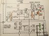
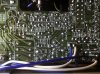

Try it.go ahead and replace TR404 with KSA992
It likely will not pop.3-4 sec. is ample time to stabilize.Not sure going to still hear the popping sound or not.
Last edited:
Good call...Your voltage measurement indicates the BC junction of TR404 might be shorted.