• The move to the new server is done. There are some software and database maintenance updates in process. This has us passing the hat around to help out. We appreciate any donations. Seriously, even a dollar helps. The payment page may be found here - https://www.audiokarma.org/support.html

Technics SU-V8 Amp - ICQ problem - dead trim pot?

Flapper

Member
Hi all,

A few years back I bought a second hand Technics SU V8 amp which quickly became my favoured amp (slightly, over a Sansui AU-317 that I also like).

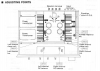
Every so often I have set the DC balance, Clamp Voltage and ICQ without problem using a multimeter and the instructions in the service manual (pasted below.)

Recently the right channel developed some distortion so I went to check all the levels and I noticed that perhaps one of the trim pots has stopped working or at least has stopped having any effect on the ICQ level of the right channel.

DC balance is still settable to 30mV using VR301 / VR302 (see below).

Left channel Clamp voltage can be set to 1mV using VR603 and ICQ then set to 40mV using VR601

Right channel Clamp voltage can be set to 1mV using VR604 (when zeroed) but then when I move VR602 to set the ICQ it won't move off 1mV. It's like VR602 has no effect any more and the sound is gritty.

I can 'remedy' this and move the ICQ reading up to around 28 mV by messing with the right channel's DC balance (VR302). This temporarily removes the grittiness, but the sound is not hi-fi and - obviously - the DC is not meant to be pushed in this way as I guess it will be pushing all sorts of other things out.

I have ordered some new 1kOHM trim pots and will replace VR602 to see if the pot has gone bad. Does this sound like it will be the culprit or does anyone have any other ideas why I'm suddenly unable to set ICQ on the right channel?

Thanks for any help.

Sam


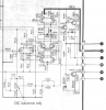
upload_2020-11-30_17-31-3.png


upload_2020-11-30_17-30-34.png
 
Register to hide this ad
ICQ = quiescent current = idle current = bias

DC Balance is DC offset
 
Ok the new trim pots have arrived and I've swapped out VR602 but still no joy. The clamp voltage can be set to 1mV by VR604 (in fact it can range all the way to 20 mV) but - as with the old pot - spinning the new VR602 does not affect the bias current (ICQ) and it will not move off of 1mV when it needs to be set at 40mV. The sound on the right-hand channel is degraded. I can make it 'better' but not right by either upping the clamp voltage to 20mv or whacking up the DC offset but it's not a good sound and is obviously not how the amp wants to be set up.

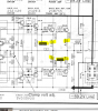
upload_2020-12-2_18-25-0.png upload_2020-12-2_18-25-59.png

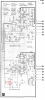
So I guess the question is where do I go from here? Could it be bad transistors? I've pasted the schematic for this bit of the amp below. I have a multimeter which I know roughly how to use. Yesterday I scored an old, working Trio oscilloscope for £15 but I need to learn how to use it. Any guidance appreciated. Thanks.

The problem in a nutshell: unable to increase BIAS / ICQ voltage in the right hand channel, and it it not due to a bad trim pot.

upload_2020-12-2_18-32-57.png
 
Have you replaced the epoxy diodes? Outputs and emitter resistors are good?

It's a pretty bulletproof unit. One of my favorites.

I would have used Bourns 3386F-1-___LF for that trimmer. It's perfect lead spacing drop in and 25 turn isn't really needed here.
 
Thanks for the reply. Yes, its a great amp that can sound glorious (to my ears).

I've done nothing except swap that trim pot. I'm going to need to go away and read about how to generally diagnose problems in the amp. A few questions:

- would you recommend replacing all the epoxy diodes on the whole board?

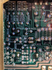
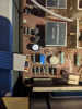
- I presume the emitter resistors are somewhere in this area of the board. I will read up, but I presume they need to be pulled from the board to be tested:

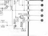
upload_2020-12-2_19-10-32.png

I'll read up on the outputs and how to test them.

Thanks for the pointers of where to look next.
 
I presume the emitter resistors are somewhere in this area of the board. I will read up, but I presume they need to be pulled from the board to be tested:
Emitter resistors are connected to the emitters of the output (heatsink mounted) transistors, see below, typically large white
ceramic looking items. Listed as 0.47ohms so ok to measure in circuit, allow for probe resistance your meter will show about 1ohm?

Measure the dc voltage at TP602 and GND/chassis. Repeat for TP604 and GND, expect less than +/-100mV (or so). Maybe
compare with TP601 and TP603 on the other channel.

upload_2020-12-3_6-40-37.png
 
An open in pull down or a short in bias transistor may be a culprit

what voltages are at Base of Q614 and Base of Q616

check health of Q316 also
 
Hi all,

I've had the amp open and done a bit of research and here are the results.

Should be set to zero volts or as close to zero as you can get +/- 10mv...

Carefully re-read the procedure...;)

Yes, thanks. I've known this in the past. Had a brain fart and forgot it, but before putting in the new trim pot I followed the instructions carefully and zeroed the DC balance. This is achieveable but it may be noteworthy that for the right hand channel (the problematic one) the trim pot has to be much further clockwise to achieve 0mV.

...Outputs and emitter resistors are good?.

With some help from mbz's post above I identified the emitter resitors and the outputs and here are my measurements:

upload_2020-12-3_12-58-24.png

Does anything look amiss here? I noticed that the resistances measured in the emitter resistors of the right (bad) channel were slightly higher than those in the left (good). Also the voltages in the outputs (I think these are outputs, mounted on the heatsinks) were slightly higher/lower in the left (good) channel than the right (bad). I presume there should be that pairing of negative and positive values?

Measure the dc voltage at TP602 and GND/chassis. Repeat for TP604 and GND, expect less than +/-100mV (or so). Maybe
compare with TP601 and TP603 on the other channel.

TP602 & Ground: 10mV
TP604 & Ground: 7mV
TP603 & Ground -16mV
TP601 & Ground 19mV

SVI2004A said:
An open in pull down or a short in bias transistor may be a culprit
what voltages are at Base of Q614 and Base of Q616

check health of Q316 also

RIGHT:
Q614: 506mV
Q616: 484mV
Q316: 1355mV

and for comparison I just took the left channel

LEFT:
Q615: 648mV
Q613: 635mV
Q315: 555mV

So perhaps there's something amiss with Q316? Or perhaps that's linked to the fact that I'm having to push the right-channel DC offset pot more to achieve 0mv (compared to the left channel).


I really appreciate all of your help guys. Thanks.
 
Last edited:
(From ground) With 0V DC offset
Base of Q614 should be 2V
Base of Q616 should be -2V
Voltage between base of Q614 & Q616 should be 4V

If there is not -2V at base of Q616 - check voltages at Q316
- check R358 and R350 - and put Q316 on transistor tester - if open, will have no pull down and render ICQ adjustment useless
 
Ah! just seen that there's more than one way of testing a transistor with a multimeter. My readings were Base to Emitter.

Now. I've attached the black lead to ground and used the positive lead to go to the bases:

Q614: 1.64V
Q616: 1.64V

both are positive

I checked the voltage at the base of Q316 and it seems very high at -64V (With Q314 at 64V) but perhaps that is normal?

I'm unsure how to check the voltage between the base of Q614 and Q616 and I don't want to short anything out. Would I put one probe on Q614 base and the other on Q616 base?

Thanks. Sam

EDIT:

R358 - 96ohms which (Spec is 82 ohms from what I can tell)
R350 - 0.56ohms on a 2k scale (Spec is 560 ohns so that seems bang on).

I do have a cheap transistor checker. Perhaps I should pull Q316 and see what it says?
 
Last edited:
With amp off, check for Collector-Emitter shorts on Q606 and Q610

if not it has surely got to be open Q316 (or R358)

with no pull down (Constant current) amp will feather +drive to establish 0v at output (dipping lower than 2V at base of Q314)

See pic for voltages associated... check voltage each side of R358

the higher rail voltages you noted may be due to higher mains voltages.. shouldn’t have any effect overall (should be same both ch)
 

Attachments

  • 4CF8CA29-2043-4060-A685-73838ED39A35.png
    4CF8CA29-2043-4060-A685-73838ED39A35.png
    288.9 KB · Views: 12
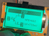
I pulled Q316 and put it on an Mtester. This is what it said:

[EDIT - wrong photo posted see two posts down]

Is this of any use?

I'll decode the rest of what you've said now!

Cheers. Sam
 

Attachments

  • upload_2020-12-3_15-18-49.png
    upload_2020-12-3_15-18-49.png
    886.9 KB · Views: 23
Last edited:
Thanks for the reply. Yes, its a great amp that can sound glorious (to my ears).

I've done nothing except swap that trim pot. I'm going to need to go away and read about how to generally diagnose problems in the amp. A few questions:

- would you recommend replacing all the epoxy diodes on the whole board?

- I presume the emitter resistors are somewhere in this area of the board. I will read up, but I presume they need to be pulled from the board to be tested:

View attachment 2052606

I'll read up on the outputs and how to test them.

Thanks for the pointers of where to look next.
Yes, replace both of them. They could be your issue.
D307/8, replace with two 1N4148 in parallel. Pretty sure it's two, but check voltage drop of old part.
 
Sorry wrong photo - this is it:
upload_2020-12-3_16-21-50.png


Yes, replace both of them. They could be your issue.
D307/8, replace with two 1N4148 in parallel. Pretty sure it's two, but check voltage drop of old part.

This gave me an idea - since the left channel is fine but the right has the problem I swapped these diodes to see if one of them was causing the problem - sadly nothing changed. I'll probably replace them anyway, as you advise

With amp off, check for Collector-Emitter shorts on Q606 and Q610

I read up and it seems this is something to check via resitances? Unfortuantely my multimeter is cheap and nasty and couldn't pull any readings from these transistors.
 
Back
Top Bottom