• Please note that Audiokarma will be offline briefly for updates early on Monday morning, September 28th.

The "$250" Amp? - 6LU8 Compactron SE, UL

Nice looking prototype chassis. I kinda like the primer chassis look.....

Is anyone in this group build have a way to breadboard and tweak the circuit prior to building a completed amplifier, using a DC tube PS?

It would seem easier to try all the suggested ideas on the fly breadboarding, determine what is best, than having to do changes to a completed amplifier and chassis.

I may have to buy a couple 6LU8's........
 
Well, this might sound nuts, but Keg and I have a crazy way of prototyping worked out. If you break down the amp, there is the PS and the signal path. One could potentially desire more or less B+ out of a power supply for experimental purposes. We will be able to do that with varying the size of the first capacitor in the power supply. We already know a rough range of power that we might want, and if we need a different power transformer then we will discover that. However, Keg believes that we will be able to get roughly the B+ we want, most likely from this combo, with enough variance in range for experimentation (it will be possible to provide for a SS rectifier, for instance).

The signal path will have the OPTs, and the 2 tubes. I guess I'm going to breadboard the amp in the sense that the entire signal path will fit on that perforated aluminum. I'm also going to make that removable, so that Keg can mod to his heart's content. Having such a small parts count makes it so that there are only so many places you could put them in the first place!

This will get passed to a few different hands before it is finished. I will make the prototype to be as modular as possible. We don't claim that we'll hit it right off the bat, so i'll build the prototype with that in mind. I'll make this as close to a breadboard on a chassis as possible.

 
I'm the one on the right with the beard. The set is of dnewma04 and my room at AK Fest '08. The little ugly brown amp is basically a RH84, which is a similar circuit to this project amp, if on a slightly smaller scale.

You take nice pictures man. You have some fun looking stuff too! Thanks for posting the link. Love looking at people's pictures. :D
 
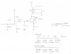
I think I have all of the parts the I need to finish the initial schematic furnished by Kegger either on order, on in house. The parts on order should all be here by Friday. Some are more critical than others. The PT should have been here by now, and that is starting to worry me, but if worse comes to worse I do have a lot of iron around here for experimentation.

I bought all of the 1W resistors for Keg's schematic in bulk, for bulk pricing. If there is a one-time "group buy" for this amp, I will use from this stock and pass the savings on to the group, so that we are not restricted to a minimum size for bulk pricing for these parts. If we overrun my stock, we'll order more in bulk. The same goes for a change in resistor value in the schematic, in case Kegger makes a change. I'll just buy more resistors. No big deal, I'll use 'em all sometime anyway.

I'm gonna put one more coat of primer on the prototype. I think I like the "primer look" on this one, and it's cheap.
 
Any tests yet?

I have an Edcor XSE25-2.5K-8 I could try with a 6AV5 in triode if anyone is curious of the results... i don't have any 6LU8s in the boxes...
 
Bricktop that should work just fine. I'm running Push Pull Triode 6AV5 with a
pair of Sansui 1000A outputs which are 5000-6600 pl to pl and it runs very
well, had it at the fest and has been my main amp for quite some time now.
 
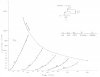
Rough curves of 6AV5GA in triode.... Pentode curves are real close to that of the pentode in the 6LU8, so these ought to be close...

Next ill put it in a circuit...
 

Attachments

  • 6AV5_triode.JPG
    6AV5_triode.JPG
    101.4 KB · Views: 127
Your Edcors should have UL taps I think as well?
Some testing in UL I'd be interested in seeing some results.

My 6AV5's are in triode with roughly 295v at the plate, cathode biased
and I believe 50v on the cathode, (Can't remember for sure right now)
 
Your Edcors should have UL taps I think as well?
Some testing in UL I'd be interested in seeing some results.

My 6AV5's are in triode with roughly 295v at the plate, cathode biased
and I believe 50v on the cathode, (Can't remember for sure right now)

Yes they have them. It's a little harder to get UL curves without special equipment. The triode info will be useful for biasing though as well. I did some bench tests with triode, UL is next. I used a 12AT7 as the driver, pretty close to the 6LU8 triode section - but the 6LU8 triode does look more linear than the 12AT7, so ya got that going for you. Not much spare gain for feedback here, so this stuff is all open loop. B+ is 225V. Bias is -37V.
 

Attachments

  • trioded.JPG
    trioded.JPG
    79.6 KB · Views: 198
And ultralinear...still through the 120 ohm resistor to the 40% tap.

Bit more distortion at low powers, but a tad more available power before 5.0% THD. The frequency response is for triode only, ignore it for UL, it is most certainly different.
 

Attachments

  • triode_ultralinear.JPG
    triode_ultralinear.JPG
    84.2 KB · Views: 153
Easy enough to try cathode feedback through the secondary... this also gives a little higher load impedance, which I think will help in UL.
 
Interesting results, the more testing the better. (keep the ideas comin)

With the 6LU8 and using a B+ of 300v will have a bit more gain for the driver
as we'll be able to get more current, plus the plate to grid feedback gives us
a bit more voltage to the front end, so we should be just about right I think.

And running the pentode section a bit harder with more current and voltage
should get us similar distortion figures at a little more power output here to.

All in all about what I would of hoped to see and were on the right track. :)

What will be a good test is implementing the plate to grid feedback and see
if the distortion improves towards full power ratings at all in this circuit here.
 
Iplayed arround withe the bias resister a bit to try and help the pssr in the first stage a bit its a bit low at -1.1db-------by changing it to47k from 100k the pssr is up to -1.49db and along with toms idea it is very good the Z out only droped about 145ohms to 3.96k--will this help?? bias resister-to 47k.
 
Last edited:
Bruce you've lost me? Are you talking the plate load 47K resistor like the schem?

Or the 510ohm bias resistor on the driver cathode or the 100K feedback resistor?

What is your supply voltage and it's topology, are you using a decoupling stage?
 
It was the bias resester that Bricktop used in his design it didnt change the the swing of the voltage very much but helped to reject some of the power supply noise in the first stage of his 12at7 circuit from -1.1db to -1,49db--and the gain only dropped about .4db I was using a Bpluss of 230 volts instead of 225 --this value doesnt change the gain or effect the performance.
 
Back
Top Bottom