• The move to the new server is done. There are some software and database maintenance updates in process. This has us passing the hat around to help out. We appreciate any donations. Seriously, even a dollar helps. The payment page may be found here - https://www.audiokarma.org/support.html

The B-2 Restoration

bobdod

Super Member
As I've written in a separate thread, I've taken possession of a Japanese market B-2. My goal is to give it a bit of a refresh and take care of any known trouble spots. I have no history on this B-2, and I have not powered it on, so don't know if any problems exist at the moment.

I was told by a few folks that it would only take 15 minutes to pull and test the vfets. Having no history on the amp, I figured that needs to be the first step, as vfet replacement would be a likely project ender for me. After getting into it, and getting the vfets out, I can see how one can do it in 15 minutes. I however, had never been in a B-2 until today, so for me it took about an hour. I made sure to prepare and set everything up ahead of time so as not to mix up the devices. After testing them with my multimeter, per echowars' instructions, I think they are ok. Or at least based on the testing I could do without more serious equipment, I will say for now that they are ok.

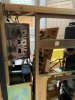
First look under the hood. A bit dusty.
29E052AB-C66F-4A46-8066-6873DB389077.jpeg

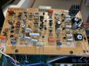
A look at the power board. No warping or signs of heat damage.
58F987C1-3BA1-41BF-8241-54427F882316.jpeg

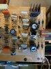
A look at the filter caps. No signs of leakage or bulging that I could see. I think I'll replace them anyway, but I think they may test good still.
E494D6E4-28B1-4036-86C3-AE405E460ED3.jpeg

My vfet container, with numbers so that I don't mix them up.
5C54548D-BFCE-4085-B10A-716AB0B7C57D.jpeg

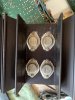
Close-ups of the devices before removal.
A3223CE2-2272-4AD0-96E8-42D80720352C.jpeg
BAFCFAF4-7D48-4EBB-8996-CEE0615FF601.jpeg

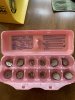
Removed devices in their storage container
47179709-CC6C-4945-ADF5-4494A95A45BC.jpeg

I have a feeling that the vfets on one side were replaced at some point. Several of the bolts holding them to the heatsinks were missing washers. They also have numbering written on them, whereas the devices on the other channel do not. The numbers are 6, 39, 7, and 33. One of them also has marking on the back, that say "IR" and something else. The device with the marks on the back had a little lower resistance measurement between drain and source (1.3ohm, where most of the others were around 2ohm). It tested in line with the other vfets otherwise.
C825A132-A7D0-464A-AE83-DFC9467B69B1.jpeg
 
Register to hide this ad
Hello

I will not use this kind of package because of the static material

Are all your V-FET good ? tested with a curve tracer ?

Any other way to test is not serious and a multimeter is OK if you want to see if they are shorted or not but that's all
 
Hey it looks like you're off to a good start with a nice looking B-2!

Contrary to what's been said, your V-FET's are safe for storage in the egg carton; they're not sensitive to static like MOSFET's are.

Testing with a mutimeter is a good start and from your readings there're fair odds that they're fine albeit it is unusual that you have one odd one since Yamaha hand selected them for good N to P Channel matching. Testing them with a curve tracer that test them with sufficient V/I (not the Atlas DCA Pro which barely turns them on) would be the best answer to check for matching. :thumbsup:

Good luck!
 
Last edited:
With no obviously shorted vfets, would it be prudent to get the unit powered up to check for other issues? Could I do this with a DBT and vfets not installed? If so, what should I be checking?
 
Testing them with a curve tracer that test them with sufficient V/I (not the Atlas DC Pro which barely turns them on) would be the best answer to check for matching. :thumbsup:

Good luck!

Unfortunately, I do not have a curve tracer. Anyone in the Philly area that has one and wants to test these?
 
With no obviously shorted vfets, would it be prudent to get the unit powered up to check for other issues? Could I do this with a DBT and vfets not installed? If so, what should I be checking?
with the VFETS OUT, you can use a variac and dbt to bring it up and reform those bulk caps. Maks sure to discharge them before you put the vfets back in. Also, keep in mind at all times that you have a 100v unit so do not go over that with your variac.

Having a 100v unit forces you to use a step down transforemer. If it is adequately sized, a step down transformer is actually preffered than plugging idrectly into the mains anyways, as the step-down acts as an Isolation transforemer as well.

You do not need to bother with matching vfets on a curve tracer at this time.Just do not mix them.
Worry about testing the vfets further or matching on a curve tracer, if the protection light remains ON or you get lots of distorsion on that suspect channel.
 
with the VFETS OUT, you can use a variac and dbt to bring it up and reform those bulk caps. Maks sure to discharge them before you put the vfets back in.

Thanks, yes I've read from other threads about the need to discharge the filter caps, and will certainly do that. I think I saw in the service manual how to do that, so no issue there.

After reforming (provided there are no issues), are there any relatively simple checks I can do, like taking voltage readings between certain points, to confirm the driver boards are ok? I've found some replacement parts on the driver board that corresponds to the channel with the replaced vfets. Several transistors were replaced, and not in an extremely neat manner to put it mildly.
AF2666EC-8962-4E18-B444-170D433883D1.jpeg
 
Thanks, yes I've read from other threads about the need to discharge the filter caps, and will certainly do that. I think I saw in the service manual how to do that, so no issue there.

After reforming (provided there are no issues), are there any relatively simple checks I can do, like taking voltage readings between certain points, to confirm the driver boards are ok? I've found some replacement parts on the driver board that corresponds to the channel with the replaced vfets. Several transistors were replaced, and not in an extremely neat manner to put it mildly.
View attachment 1975495
yes, you will nedd to do some work on the right channel driver board.
post a close-up photo of the bottom of the chassis. As you face the amp, the bottom of the capacitor bank, near the right transformer base
 
post a close-up photo of the bottom of the chassis. As you face the amp, the bottom of the capacitor bank, near the right transformer base

photos of chassis as requested.
519559DA-0E13-4EDE-B36D-FA9F01F34CF8.jpeg ACADE86D-D3FD-4628-8E8B-F3F1CDAC99D8.jpeg BE2CC9CF-5A72-4A53-A10F-6247F6E6575E.jpeg CA450B15-0602-4D48-94B8-2A1DA384DE50.jpeg
6FE9A4AE-2C59-4647-8850-AE75ABA635D1.jpeg FB5601E9-80A4-4D48-9BEB-0681737605A7.jpeg

I’ve also taken an initial look at the right driver board and added photos as well. From what I can tell, the following have been replaced:
- TR122 and TR124: will need to remove to see what the replacements are.
- TR121 and TR123 have been removed at some point.
- TR114: has been removed at some point. 2SC1775 currently installed. Not sure if original or replacement.
- TR115: has been removed at some point. 2SC1775 currently installed. Not sure if original or replacement.
- TR112: C1850 currently installed.
- D111: looks like replaced in kind, or removed and reinstalled.
- looks like some of the white micron labeled resistors were replaced in kind or removed and replaced.
- I am aware of the green wire being disconnected from the board.
AA147243-9FC2-4BAF-B667-E36D2CFCD706.jpeg
0AB967F9-4643-4AF2-B154-C2986924CC0C.jpeg
D7A4F757-BE57-4817-AC61-6C84CE1D31C6.jpeg
 
Too bad. I'll state the obvious by saying that it looks like there was a serious failure in the right channel and the tech didn't get everything sorted out properly before he powered it on perhaps even with the V-FET's installed. Looks like you have some work ahead of you.

I'd be wanting to prove that all the V-FET's are still good and properly matched before going much further but that's just me ...

Any evidence of leaky main caps?
 
I'd be wanting to prove that all the V-FET's are still good and properly matched before going much further but that's just me ...
yeah, in light of the quality of the "repair" I would too consider testing the vfets on a curve tracer before spending time to fix that channel.


photos of chassis as requested.
I do not see clear signs of leakeage.
However, I do see a spot of rust towards the middle which could be benign, but I would pull the caps for further visual inspection and testing before I would use them.
 
Unfortunately, I do not have a curve tracer. Anyone in the Philly area that has one and wants to test these?

Not sure that testing with a curve tracer is going to be possible locally. I don’t know anyone local to me. I could maybe ship them, but that sounds risky as well, and I don’t know who would be up for testing them and has the right equipment.
 
I do not see clear signs of leakeage.
However, I do see a spot of rust towards the middle which could be benign, but I would pull the caps for further visual inspection and testing before I would use them.

no rust on the chassis, just dirty. I have not cleaned anything yet. I agree the repairs are questionable, but not willing to jump to the conclusion that they weren’t effective. I am guessing there was a major failure that took out the vfets on the right channel, resulting in repair of the driver board and replacement of the right channel outputs. It might make sense to install correct transistors into the right driver board, check the other components, and try reforming/powering up without the vfets. I’ll keep looking for someone to test with a curve tracer, but if that isn’t possible, I think this is the next possible option.
 
no rust on the chassis, just dirty. I have not cleaned anything yet. I agree the repairs are questionable, but not willing to jump to the conclusion that they weren’t effective. I am guessing there was a major failure that took out the vfets on the right channel, resulting in repair of the driver board and replacement of the right channel outputs. It might make sense to install correct transistors into the right driver board, check the other components, and try reforming/powering up without the vfets. I’ll keep looking for someone to test with a curve tracer, but if that isn’t possible, I think this is the next possible option.

One of the few reasons B-2 would fail is because of the driver transistors. The driver transistors (2sa1452/2sa810) in the B-2 are ill-faited and need to be replaced. Same transistors used in the B-1 driver board show similar failuire tendencies...except their faiuire in the B1 comes with even more tears :(
The replacements Yamaha offereed (Panni 2sc1953/2sa914) seem to be very close in speciffications, but very stable. Yamaha used them as replacement for the B-1, B-2 and as standard drivers in the B-3.

hint: someone with a curve tracer responded to your thread earlier....
This is the time you might want to consider shipping that entire B-2 for a full repair and restoration ...after you first send out the vfets for testing...(no, not to myself as I work mostly on my units).

my 2c
 
Last edited:
I am going to try to get back into this thing. Testing the vfets is going to be impractical, as it would require international shipment, so I will instead proceed to test the power board and driver boards without the vfets installed. My plan is to proceed in the following order:

1. Replace 2SC458 LGs (if any are present) in the power board and thoroughly test it, with the driver boards and vfets out.
2. Check components on the driver boards, especially the right board, since it has TR122 and TR124 replaced with 2SA914R.
3. Introduce the driver boards to the unit with the vfets out and test.
4. If no issues are found on the driver boards, replace the TR121-TR124 on both driver boards. I am thinking this makes sense to do prior to introducing the vfets as currently there is a combination of 2SA914/2SC1452 on the right board and 2SA810/2SC1452 on the left board. I've seen several substitutes suggested, so will need to determine what is available and suitable.
5. test the driver boards again with vfets out
6. introduce vfets and give it a listen. I realize that if the vfets are problematic, the above efforts will be wasted, but I will also have learned and furthered my knowledge for future efforts.
7. If vfets prove to be ok, proceed with a more thorough rebuild.

I will also test the filter caps and be sure to properly discharge between steps. I am hoping that if I go slow, lay out my plans, and report on progress in the thread, I'll get enough support to keep me on the right track.

Before I proceed, I'd like to reform the unit with a variac. I've never worked with a 100v Japanese market amp before, so I want to confirm the correct way to set this up. I am looking for feedback/confirmation on the following assumptions:

1. I assume that I don't need to use a step down transformer since I am using the variac and staying well below 100V.
2. I will connect a DBT to the variac and then the B-2 to the DBT. This way I can have visibility to voltage and current draw.
3. Unit will be fully assembled for this, with only the vfets being out. All boards will be installed, all wiring connected, bridge boards installed, and heat sinks installed (to connect the chassis ground from the filter cap board).
 
Last edited:
Do not go below 100v when you install the V-fets!!! And not sure if a DBT is advisable either with he V-fets installed.

To be honest I don't think going below 100v for any test is good as some circuits may need a full voltage for proper testing.

So set your variac to 100vac and leave it there and make sure is set up so you can't accidentally change it once the V-Fets are installed.


Athanasios
 
Do not go below 100v when you install the V-fets!!! And not sure if a DBT is advisable either with he V-fets installed.

Athanasios

I am not doing anything with vfets installed yet. The variac will be used to reform capacitors, at a low initial voltage. No variac or DBT when I do eventually get to a point where vfets are reinstalled (will be using a step down transformer). For testing though, I think a DBT is useful, even with a variac. If there is a short somewhere, the DBT may reveal that.
 
Back
Top Bottom