• The move to the new server is done. There are some software and database maintenance updates in process. This has us passing the hat around to help out. We appreciate any donations. Seriously, even a dollar helps. The payment page may be found here - https://www.audiokarma.org/support.html

The KA-2000 restoration

You are looking at the wrong R11, the power section that contains the 0.47Ω resistors seems to be separate, actually on a tag-strip as in the picture & schematic posted by Hopjohn and quoted by you. The 2.2KΩ resistors are correct - look near Q3 on the schematic, you'll find the 'other' R11 which is 2.2KΩ (red-red-red-silver) in your picture in post #62.
thanks for reply! my bad !
 
I have not replaced that part before and there is no info on it. My educated guess is the 2 diodes are acting as a thermistor used to track temperature to create a voltage drop when unit is turned on to reduce startup stress. This part seems similar to the later SVT-3/SVT-4 diode. You can try taking before/after measurements while replacing with two 1n4003-1n4007 series diodes.
 
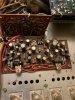
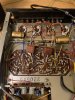
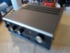
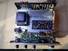
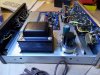
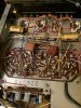
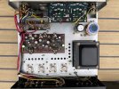
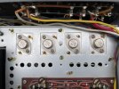
Looking at one of these to possibly buy it and it was gone thru with new parts. Here is a few pics of it.
 

Attachments

  • s-l1600 (2).jpg
    s-l1600 (2).jpg
    93 KB · Views: 91
  • s-l1600 (1).jpg
    s-l1600 (1).jpg
    129 KB · Views: 95
  • s-l1600 (3).jpg
    s-l1600 (3).jpg
    121.2 KB · Views: 85
  • s-l1600 (4).jpg
    s-l1600 (4).jpg
    115.9 KB · Views: 82
  • s-l1600.jpg
    s-l1600.jpg
    131.3 KB · Views: 89
Hi, I have one of these amps. Is it normal for it to make a fairly loud thump through the speakers when powered on and off?
 
Hi, decided to give this restoration a go on my trio KA2000, as I was listening to it recently and the left channel made a pop and went dead. I am 20 years old so am new to restoring amplifiers but I would love to get this amplifier going again. I am in the process of following along hopjohn’s restoration posted here, and once I had all the components on the main amp board (minus the new trimmer pots) I decided to try playing music through the amp to make sure I hadn’t damaged anything. Just as before, the right channel worked fine and the left was silent, unless I cranked the left channel right up, which gave me quiet distorted sound with a loud pop for each drum beat in a song. I initially rushed into thinking that the germanium 2SB89A transistor on the left channel had gone bad, but after removing and checking it with a transistor tester it came back ok. I then checked to make sure I soldered the KSC1845F transistors in the right way round, and decided to change the left one for a new one in case I damaged it from heat or static. Upon testing again, both channels worked, but within 2 seconds the left began to fade back into its original state.
I decided to compare the voltages of both KSC1845F transistors on the amp board, and found that the collector on the right channel transistor was getting around 12 volts, and the one on the left was getting 19.8! It appears that R17 connects the collector to a 20v rail on the main board, so I checked R17 and it was fine. I tried swapping output transistors and it made no difference, I fed in a 1000hz signal into the amp and traced it to the main amp board with a little oscilloscope, where it was delivered via the shielded cable from the tone control board, but never made it through to the output transistors.
I know this is an older thread, but I’d be very grateful for your help, as I’ve hit a bit of a dead end with this. I’ve attached a few pictures of the board, please excuse the bad soldering I will hopefully get better at it, all the bestimage.jpgimage.jpg
 

Attachments

  • image.jpg
    image.jpg
    156 KB · Views: 15
Wabr101 checked those black wires, they appear to be ground wires for connecting the board to the negative side of the power supply, they’ve always looked like that. I am just a bit confused why one KSC1845 transistor is getting more voltage to it’s collector than the other, would make sense if the transistor was bad and creating a load on the resistor to make a voltage drop, but I have replaced this transistor twice, with always the same result
 
Took another look at the amplifier today, turns out I made a silly mistake and soldered both leads of a resistor to ground instead of one going to ground and one to where it was meant to go, fixed this mistake, and now both channels are working well, I can now continue with the restoration
 
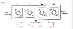
I present mine to you. After changing the capacitor, I obtain these values. Should I leave it this way or try to change it?
 

Attachments

  • IMG_1937.JPG
    IMG_1937.JPG
    125.3 KB · Views: 66
  • IMG_1974.JPG
    IMG_1974.JPG
    167.6 KB · Views: 64
  • IMG_1977.JPG
    IMG_1977.JPG
    140.7 KB · Views: 69
  • Capture d’écran 2023-07-20 à 21.20.35.png
    Capture d’écran 2023-07-20 à 21.20.35.png
    107.2 KB · Views: 66
Your values look a little light, try swapping out the two rectifier diodes (D1,D2) with a fresh general purpose 1N4004-1N4007 diode and see if voltages return to normal.

ka-2000.jpg
 
You may have a short or incorrect wire hookup dragging it down.

Check continuity of all ground points to chassis.

I would build a dim bulb tester to verify if its a short.
 
Is it necessary to add IN4007 diodes in parallel with 0.022uf capacitors on my example, it did not have any?
 
Back
Top Bottom