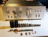
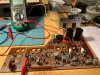
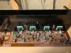
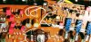
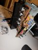
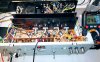
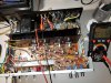
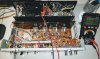
Completed my KA-3500 restoration project. Big thanks to
@hopjohn for the nice guide, that was a huge help in getting be through my first full restoration project. Unit is back up and running and sounds great.
I am attaching my BOM worksheet that shows the parts Hopjohn recommended and the ones I actually used. This includes the p/n and a link to them on Mouser. Hopefully this could help some future newbie tackle this restoration.
https://docs.google.com/spreadsheets/d/1STxtiiORratVAdV_3YjveIc_sozHsMJco4q5JwZIv_4/edit?usp=sharing
Some notes and questions I had from doing this project, feel free to comment:
1. Although I based much of what I did on Hopjohns guide, I stuck to the capacitors that more closely matched the uF of the originals. I am sure Hopjohn had good reason for using the higher uF, but being new to restorations it was not clear to me what the benefits would be to the higher values. Also, I had already replaced the capacitors in the power supply with originals values months ago as they had failed and caused distortion. I was not sure if they all needed to be upgraded in the same way. In the end I decided I would be happy to have it sound as good as original and did not want to make too many changes.
2. For gain matching the input differential pairs Qe1/Qe3, this became a bit of a rabbit hole for me… I bought the parts and purchased a multifunction tester to gain match them. The more I looked in to this, the more opinions I found on how to do it correctly. I quickly found from my tester how temp sensitive they are. I tried to isolate them but results were inconsistent. I found that some build special testers boards just for the gain matching and found many differing opinions on those. Finally, I decided to move forward to replace all the other parts I have listed and that I would then test the DC Offset and decide from there. So, my results are: 9.6mV right channel and 11.2mV left channel. I decided not to touch it. Would love to hear any comments or suggestions on this.
3. Reapplying the thermal paste on the output transistors, this again turned in to a bit of a rabbit hole for me. I purchased the Wakefield 120 compound and was planning to do that last after everything was tested and working. Lots of opinions on if you should replace it or not, but it makes sense to me since you’re in there just do it. However, the more I looked in to this I became concerned that I might break the mica insulators trying to remove and clean them. I decided I would buy replacements just to be safe. Turns out insulators just like the output transistors themselves are unobtanium. So, I decided not to take that risk as all appears to be working as it should. I have a temperature probe on my DMM and have checked after running the am hard for hours and the transistors stay about the same temperature as the heat sink with in 1-2 degrees C. Again, would love to get input / feedback on this.
4. The Bias Trimmer was the last thing I replaced and I had a lot of concerns about setting them low and getting them in correctly so that low was not high if you know what I mean. I did all this work and did not want to blow up the amp now.. I’m sure this is just a newbie concern as it was not clear for me and I spent a lot of time to be sure I understood this before I installed them. You can see from all the pictures I had at the end of my BOM that I probably spent a little too much time on this. Maybe it will help someone else work it out faster first time around.
5. Question related to measuring Bias: Should bias be set when amp is cold? What is the proper procedure for measuring the Bias? I read that you should set it from a cold start, but does that mean within +/- 10min? Should both channels be tested from a new cold star? This is what I did: Cold start amp with DMM connected and let it run for 1 min for each channel. Is this the right way to do it? I see that it will continue to drift as the amp warms up, is this normal?