• The move to the new server is done. There are some software and database maintenance updates in process. This has us passing the hat around to help out. We appreciate any donations. Seriously, even a dollar helps. The payment page may be found here - https://www.audiokarma.org/support.html

The Kenwood KA-3500 restoration

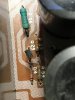
What @rickl said. Those two cap leads twisted together were probably soldered to a screw close by (within reach of the cap leads). There's a faint possibility that when you fix that, your other "pop" issue may rectify itself.

I ran a small lead wire to them and attached them to a common ground point on the chassis near by. I also touched up some solder on the preamp board with the switch. Those seem to have taken care of my issue. I'm going to put it's through it's paces on the bench before I call it complete just to make sure.

Thank you both for the assistance.
 
Hello! I have to say that this is a great thread. Thanks hopjohn for the great details.

I just started restoration on a KA-3500 and mine has 2SB817 and 2SD1047 main output transistors. It looks like they they were replaced at some point. The jumpers on the transistors look pretty rough and I can see an unused hole from the bat-wing transistor under one end of the transistors. There’s also a sticker for a (now closed) local repair shop on the back of the enclosure and I can’t find any other obvious repairs. The jumpers on the transistors look a bit dodgey. I haven’t measured much yet, but they’re working fine.

A9EB1802-BB31-49A4-AD8C-65B269F6BC54.jpeg
44516FB4-0847-4F76-B763-38EF4C78840D.jpeg
 
@masoste, the outputs blew and the repair shop fixed it with what they had. I've seen worse. here is how i did a 5700 with heat shrink. Not all shops want to take the time.

Since it works, I'd leave it. if you decide to improve it, this is a great thread to help you get the most from these little amps.

The KA-3500 can be a nice sounding amp. I have a similar 5700 in my main living room.
 
Yeah! The detail in this thread is really good. I just started going over my KA-3500 and have ordered a few parts to get it tuned up. I think I’ll leave these output transistors for now. I’ll try to give an update or two on how things go.

I’m looking for a replacement for one of the toggle switch knobs. I think that the Kenwood part number is k27-0038-04. Any suggestions on where I could look to find one would be appreciated.

91F49F96-3302-4B2C-8E75-C2FE27C846E0.jpeg
 
7A8EDF8A-6F0B-4908-99DC-2E1587F402E0.jpeg I think I’m getting close. I have all the listed caps and diodes replaced.

I replaced the trimmers, changed Re 15 and 16 to 150ohms, and set the bias but I’m getting more DC offset on one channel than the other (66mV on one side and a respectable 5mV on the other). I don’t have one of the transistors for the muting circuit or the suggested KSA992FB for Qe1, Qe2, Qe3, Qe4 yet.

I’m curious if other folks have had a similar difference in DC offset. I think I saw someone who had something similar that they traced back to a bad Qe9 or Qe10.
 
i came across this by accident- I was looking for some info on the 3500 which ive had some years now and its developed a crackly which gets quite load when its turned on cold- then will disappear, never to return . My obvious plroblem is its in the garage with all my other 'old hi-fi' that my wife refuses to entertain indoors anymore. So, it gets extrems of temperature and dust. Facinating stuff- I thought these amps and accessories would be popular as they are fairly robust giving that they are over 40 years old now. i think I paid £25 for my original 1500 from Comet.
Other than blown it out and sprayed the pots, Ive not found anything array. I checked and tweeked the bias but it want overly high. Caps 'look' ok. So, I repalced the LED with a blue one, just becuase my cd/dvd juke-box has blue...
 
I'm currently doing my first recap / renovation and working on not one but two KA-3500 (both in amazing physical shape).

Two questions on doing this recap:

Q1. The two amps are about 190,000 apart in serial numbers. The older amp has a transistor and resistors on the Power Amp at R53, R54, D54 & Q25. This is different than any photos posted on this thread (photos below) and from the "newer" version of the amp. Are these needed since the other amp doesn't have them?

KA-3500 Newer.jpg KA-3500 Older.jpg

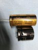
Q2. Some how I ended up with two different sets of caps for C29 & C30 of the power amp. Do I need the thicker legs in the shorter all black cap or can I use the skinnier legs like the Gold Caps?


KA-3500 Caps.jpg

Thank you to @hopjohn and @JRH99 for the images and Google Spreadsheet. I would never have been able to do this without your instructions.

Tom
 
Q1. The two amps are about 190,000 apart in serial numbers. The older amp has a transistor and resistors on the Power Amp at R53, R54, D54 & Q25. This is different than any photos posted on this thread (photos below) and from the "newer" version of the amp. Are these needed since the other amp doesn't have them?

I'd look at the board model number (X07-1470-XX). My guess they are different and therefore one had the PS regulation and one doesn't. I wouldn't worry about that.

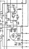
Does the schematic below look like the components? You could measure pints 8-10 and to verify B+ and B-.

upload_2022-1-11_8-33-25.png

Q2. Some how I ended up with two different sets of caps for C29 & C30 of the power amp. Do I need the thicker legs in the shorter all black cap or can I use the skinnier legs like the Gold Caps?

Ce29/Ce30 are the PS caps off the bridge. it would be nice if they were the same to make sure you have B+ and B- the same (age the same, drift the same, ...). But it probably doesn't matter. Try it and see how it works. You can always re-order one when you get parts for your next project.

I've only fixed/rebuilt 2 KA-3500 amps (at different times) and 2 KA-5700 amps so I'm probably not the expert.
 
I shouldn't have looked here. :) I'm in the process of getting a KA-3500 for a bedroom system, and was planning on just keeping it as stock as possible. It may be a month or more due to me getting from a buddy and it's going to get checked out before coming to me. But looking at this thread ... oh, it's going to inspire me to find a window of time next Spring and just get it done.
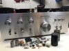
I have worked on my gear before, so not scared of that ... just not needing another project just yet. But now I know where to go when I'm ready. @hopjohn did such a nice job of documenting his work. I don't see that he's popped back on this thread recently, but kudos to him, and to the rest of you who have jumped in to add details of your own build. I hope if anyone decides to tackle this, that they read through the whole thread to make sure they understand some of the variables that exist.
 
This was my first recap and the hardest part is not being able to access the bottom without taking it apart oh, and getting all the parts. Mouser is out of some stuff until July.

ka-3500.jpg
 
It really changes daily. I couldn't get several of the resistors or transistors from either Mouser or Digikey and there weren't any back up options. Supply chain....
 
Recap/ Upgrades Continued

Power Amp X07-1470-10 (Power Supply)

Ce29/Ce30 6800uf 42V 30mm x 50mm 14mm LS (3rd pin is for support only) > 10000uf 50V Nichicon KW 25mm x 50mm leaded 12.5mm LS fits fine
Ce31/Ce32 330uf 35V 16mm > 470uf 63V PM 16mm
De1 S5VB20 200V 6A > GBPC3504W 400V 35A Bridge Rectfier (Observe polarity! Mount with 25mm breathing room above board)
De5/De6 CZ-245 24.5V 2A > 24V 3W 1N5934BRLG (Observe polarity! Mount with 10mm breathing room above board)
Re55 390 1W Check Value, replace if necessary with 2W
Re56 330 1W Check Value, replace if necessary with 2W
Re57 1.8K 1W Check Value, replace if necessary with 2W


Be sure to remove all the glue once the these four supply caps are uninstalled. De5 got slimed as shown below and its leads were starting to corrode. Remember the original main filters have a third pin which is used for support only. The replacements do not require this.
1vQDzKr.jpg

B1D3q2I.jpg

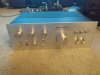
I just got a KA-3500 that was checked out by a tech I trust. He's in another state, and at the time, my main objective was to make sure the unit checked out before shipping to me.

The unit sounds good. Amazingly good compared to my expectations, never hearing this line of Kenwood. I know at some point, I will want to do a full recap for future reliability, and if the sound quality doesn't get better than it is, so be it, I like it just fine. But looking at this power amp board, it would be easy to tackle and get this part done ... part of my presumption is that if any board will fail in the near future, this might be the first to go, simply because of what it does, and having more current going through those big caps. Am I wrong in thinking there is no downside to just updating this board?
 
The 3500 doesn't have a removable bottom plate like the 5700. This adds a bit more work.

AK is a big proponent of recaps. I've only done 4 but all of them didn't work when I got them. After I fixed them, I updated a few components since they were apart.

Maybe others will commit but I've not replaced only one section (ps, tone, phono, pre, amp). I focus on power supply and signal path.

Have fun with your ka3500
 
Good point. I have always tackled the whole unit. I was letting my brain get distracted. It sounds impressive as is, so I'll enjoy it as is. Thanks for the nudge :)
 
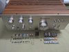
I did it! This was a multi-day process with multiple part sources and still ended up paying more on shipping charges than the parts themselves. Also followed the advices mentioned here (muchos gracias) and got a low and even 2.8mV of DC offset on both channels. The big caps still tested fine (uF, ESR) with no signs of leakage, so it remained. Of course with all the internal work, some mods on the outside was in order including the "genuine" walnut vinyl wrap. ;)

PXL_20220520_035116111.jpg
PXL_20220520_002313799.jpg
 
Last edited:
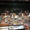
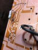
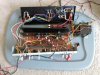
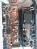
just got the ka3500...took a few minutes to figure out that no power might be the fuse or bridge rectifier. replaced bridge rec 200v/ 6amp and there's sound! new caps, a few resistors and diodes...shazam!
 

Attachments

  • IMG_20220720_220001942.jpg
    IMG_20220720_220001942.jpg
    134.1 KB · Views: 74
  • IMG_20220720_220006020.jpg
    IMG_20220720_220006020.jpg
    139.8 KB · Views: 64
  • IMG_20220720_220011191.jpg
    IMG_20220720_220011191.jpg
    137.4 KB · Views: 66
  • IMG_20220720_220034985.jpg
    IMG_20220720_220034985.jpg
    117.2 KB · Views: 63
  • IMG_20220720_220218023.jpg
    IMG_20220720_220218023.jpg
    58.3 KB · Views: 68
  • IMG_20220811_141435661.jpg
    IMG_20220811_141435661.jpg
    32.5 KB · Views: 64
  • IMG_20220811_141425230.jpg
    IMG_20220811_141425230.jpg
    56.3 KB · Views: 66
  • IMG_20220811_132111516.jpg
    IMG_20220811_132111516.jpg
    31.9 KB · Views: 66
  • IMG_20220811_132104524.jpg
    IMG_20220811_132104524.jpg
    34.1 KB · Views: 69
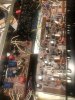
after the recap, took a few days for the sound to open up- not bad with quality caps. filter caps need increasing from stock. cutting the transformer wires and removing it, is the easy way to service it.
 

Attachments

  • IMG_20220826_225225263.jpg
    IMG_20220826_225225263.jpg
    22.8 KB · Views: 55
  • IMG_20220826_115709717.jpg
    IMG_20220826_115709717.jpg
    65.5 KB · Views: 61
  • IMG_20220826_223409781.jpg
    IMG_20220826_223409781.jpg
    22.5 KB · Views: 55
Back
Top Bottom