I had purchased a MAC 1900 that cosmetically was very nice, but internally was an absolute disaster. Took on this project and I hope that some of the work I did might help others.
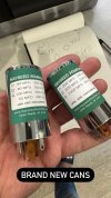
First off, I replaced some of the key transistors (orange/yellow dot, flying saucers, etc.) and changed all the electrolytic capacitors (including main filter capacitors) on all boards. I chose not to change any of the cap values from the original although some people do. I had Hayseed Hamfest stuff new chrome cans for me because bypassed cans look ugly. I also upgraded all incandescent lamps with LEDs throughout. You don't have to get these from eBay. I used a Keiurot LEDs that you can find on Amazon for around $10.00 (pack of 15). Yes it's a challenge to change these. You have to dismantle the AM/FM pointer wire and re-thread it. If you're not comfortable doing this, then pass on this.
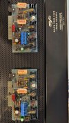
Changed the output transistors to new OnSemi MJ15003, added new mica insulators and thermal paste. DeOx'd all the switches, bass/treble faders, and input selector.
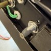
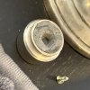
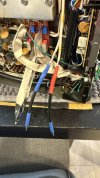
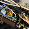
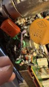
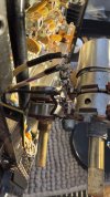
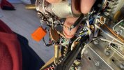
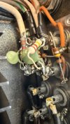
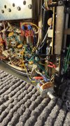
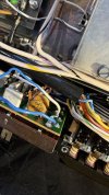
Here's where it got tricky. The volume and balance pots were toast. Not only were they toast, but someone had put all kinds of mixed capacitors and resistors across the volume and balance pots to "correct" the problem (see photos). They also bypassed the preamp in/out section with a ceramic cap and resistors. This looked like some kind of improvised treble bleed circuit. It was brutal looking and even more brutal sounding with tone and volume intensity changing at different volume levels for each channel.
I had to strip all of this garbage out and find a solution.
According to the schematic, the balance pot is a dual gang 500KOhms pot with each gang wired opposite one another to get that balance effect. Lug 1 (3) is the green or green-white wire from the audio in. Lug 2 is where the 0.22uF capacitor (tropical fish cap) is connected. Lug 3 (1) is ground. If you have any lag due to tolerance differences between the gangs then you never truly get "balance". Most of these 50-year-old pots are in bad shape, if they're working at all.
The 800KOhms volume pot, also dual gang, but wired the same on both gangs. Lug 1 connects to the other leg of the 0.22uF capacitor. Lug 2 connects to the coaxial that takes the signal to pin 7 on each respective preamp board. Lug 3 is ground. Back of the pot has a switch with AC power wires connected. This is shielded. Finally there are the loudness taps (blue and blue/white) for each gang.
With a defective balance pot (irreplaceable I'm told) and a defective volume pot (only one option McIntosh aftermarket 750k Precession Electronics pot), I was stuck.
So here's what I ultimately came up with:
1) Power: I cut the and twisted the two wires together with a beret. These were tucked into the back of the receiver, away from audio signals. I use the power bar to turn the receiver on and off now. I actually use a WiFi remote to turn the power bar on and off c/o Wemo.
2) Balance: I'm pretty sure that I can find a pot and make it work, but I chose to build a small circuit on a Gikfun Mini Solder-able Breadboard and anchor it to the AM board. I created identical channel balance by using two 500KOhms Bournes trim pots (one per channel) and set them to exactly 250KOhms each. Wired everything to the board to match the schematic. I don't play with my balance ever on any of my receivers so why not have it fixed?
3) Volume: I purchased a very expensive aftermarket pot form McIntosh that was total crap. It did not track well at all. I returned it and settled on an Alpha Dual Gang Solid Shaft Pot 1M for only $5.00. I believe I purchased the A1M linear instead of the logarithmic BM1 taper by mistake. But I didn't find it to be that big a deal to be honest. Lug 1 is connected to the 0.22uF/100V WIMA MKP4 cap, Lug 2 to the coaxial wire that goes to pin 7 on the preamp boards, and Lug 3 is ground. The two wires for loudness were soldered to the tone board. So now the loudness button works in reverse. Loudness is now manual, no taps. Not a big deal.
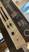
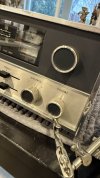
I epoxied the existing disconnected balance pot to the centre position so that I could still keep the cosmetic integrity of the unit with an option to change it for a real pot down the road if I wanted to. The new volume shaft is short, round, and solid. I tapped it with a Dremel drill and put a screw in. Next, I removed the D-clip from inside the original volume cap and added J-B Weld 8267 Steel Stick Steel Reinforced Epoxy. Stuck the cap over the screw that was screwed into the pot and let it dry.
And that's how I got this broken down MAC 1900 working like new again - for cheap. Let me know if you have any comments or questions.
P.S. My coaxial wires ran short so I extended them with wire and wrapped the wire with Faraday tape. Also used Faraday tape over the WIMA caps for added shielding. Seems to be working great. Will likely go back one day and run brand new coaxial wires from the the preamp bus to the volume pot.
First off, I replaced some of the key transistors (orange/yellow dot, flying saucers, etc.) and changed all the electrolytic capacitors (including main filter capacitors) on all boards. I chose not to change any of the cap values from the original although some people do. I had Hayseed Hamfest stuff new chrome cans for me because bypassed cans look ugly. I also upgraded all incandescent lamps with LEDs throughout. You don't have to get these from eBay. I used a Keiurot LEDs that you can find on Amazon for around $10.00 (pack of 15). Yes it's a challenge to change these. You have to dismantle the AM/FM pointer wire and re-thread it. If you're not comfortable doing this, then pass on this.
Changed the output transistors to new OnSemi MJ15003, added new mica insulators and thermal paste. DeOx'd all the switches, bass/treble faders, and input selector.
Here's where it got tricky. The volume and balance pots were toast. Not only were they toast, but someone had put all kinds of mixed capacitors and resistors across the volume and balance pots to "correct" the problem (see photos). They also bypassed the preamp in/out section with a ceramic cap and resistors. This looked like some kind of improvised treble bleed circuit. It was brutal looking and even more brutal sounding with tone and volume intensity changing at different volume levels for each channel.
I had to strip all of this garbage out and find a solution.
According to the schematic, the balance pot is a dual gang 500KOhms pot with each gang wired opposite one another to get that balance effect. Lug 1 (3) is the green or green-white wire from the audio in. Lug 2 is where the 0.22uF capacitor (tropical fish cap) is connected. Lug 3 (1) is ground. If you have any lag due to tolerance differences between the gangs then you never truly get "balance". Most of these 50-year-old pots are in bad shape, if they're working at all.
The 800KOhms volume pot, also dual gang, but wired the same on both gangs. Lug 1 connects to the other leg of the 0.22uF capacitor. Lug 2 connects to the coaxial that takes the signal to pin 7 on each respective preamp board. Lug 3 is ground. Back of the pot has a switch with AC power wires connected. This is shielded. Finally there are the loudness taps (blue and blue/white) for each gang.
With a defective balance pot (irreplaceable I'm told) and a defective volume pot (only one option McIntosh aftermarket 750k Precession Electronics pot), I was stuck.
So here's what I ultimately came up with:
1) Power: I cut the and twisted the two wires together with a beret. These were tucked into the back of the receiver, away from audio signals. I use the power bar to turn the receiver on and off now. I actually use a WiFi remote to turn the power bar on and off c/o Wemo.
2) Balance: I'm pretty sure that I can find a pot and make it work, but I chose to build a small circuit on a Gikfun Mini Solder-able Breadboard and anchor it to the AM board. I created identical channel balance by using two 500KOhms Bournes trim pots (one per channel) and set them to exactly 250KOhms each. Wired everything to the board to match the schematic. I don't play with my balance ever on any of my receivers so why not have it fixed?
3) Volume: I purchased a very expensive aftermarket pot form McIntosh that was total crap. It did not track well at all. I returned it and settled on an Alpha Dual Gang Solid Shaft Pot 1M for only $5.00. I believe I purchased the A1M linear instead of the logarithmic BM1 taper by mistake. But I didn't find it to be that big a deal to be honest. Lug 1 is connected to the 0.22uF/100V WIMA MKP4 cap, Lug 2 to the coaxial wire that goes to pin 7 on the preamp boards, and Lug 3 is ground. The two wires for loudness were soldered to the tone board. So now the loudness button works in reverse. Loudness is now manual, no taps. Not a big deal.
I epoxied the existing disconnected balance pot to the centre position so that I could still keep the cosmetic integrity of the unit with an option to change it for a real pot down the road if I wanted to. The new volume shaft is short, round, and solid. I tapped it with a Dremel drill and put a screw in. Next, I removed the D-clip from inside the original volume cap and added J-B Weld 8267 Steel Stick Steel Reinforced Epoxy. Stuck the cap over the screw that was screwed into the pot and let it dry.
And that's how I got this broken down MAC 1900 working like new again - for cheap. Let me know if you have any comments or questions.
P.S. My coaxial wires ran short so I extended them with wire and wrapped the wire with Faraday tape. Also used Faraday tape over the WIMA caps for added shielding. Seems to be working great. Will likely go back one day and run brand new coaxial wires from the the preamp bus to the volume pot.
Attachments
-
 30684A18-9D69-42F9-ABE7-6F84DCDE591E.JPG97.9 KB · Views: 52
 -
 IMG_3012.jpg98.7 KB · Views: 52
 -
 IMG_3016.jpg97.5 KB · Views: 48
 -
 IMG_3025.jpg100.7 KB · Views: 47
 -
 IMG_3032.jpg99.8 KB · Views: 50
 -
 IMG_5982.JPG133.7 KB · Views: 50
 -
 IMG_3725.jpg154.1 KB · Views: 52
 -
 IMG_3727.jpg77.6 KB · Views: 51
 -
 IMG_3729.jpg94 KB · Views: 46
 -
 IMG_3047.jpg122.6 KB · Views: 53
Last edited: