trainbuftony
Electron Herder
Preamps, a controversial subject, where does a person start? Well suffice to say I'm not convinced that I own the best, and i'm not convinced I ever will. After several experiences building and modifying preamp stages I feel like I have a grasp on what sounds good and what I like. Please bear with me, the incoherent rambling will all come together. Early on I learned that trying to design everything from scratch is a fools errand. If someone has already done it well, improve upon their work...
One of the first preamps I got my hands on was a Dynaco PAS3. I was inexperienced and eager to make this thing sound fantastic, like everyone claimed it would. I yanked the boards, tone controls and almost everything else out, made extensive modifications to nearly every aspect of the preamp, and never did fall in love with it. Moments of sonic euphoria yes, but a undying long term affection, definitely not. I am at a point with it where it works flawlessly and is very low noise. I'm calling it done and the lesson learned is that the PAS, when used as a chassis is an overpriced chassis.
I kept playing with amps, desecrating a few organs and fiddling with their guts is fun for me! Next on the list of projects was a DIY line stage. The plans on DIYaudioprojects.org seemed simple and the cost of entry was lower than what I had into my PAS. It used SRPP 12AU7s which i have plenty of, and once i built it it actually sounded really good to my ears! I made a mental note of the success. This SRPP stage is cheap enough to build, and sounds really good. It has low output impedance and will drive 2 pair of amps. It seemed to me at the time to only be missing one thing. An RIAA phono-stage for all of us REAL audiophiles. (kidding) . I took note also that I may want to use it as part of a larger build someday.

A friend of mine and fellow Audiophile calls me up one day and he has 2 HH Scott LK72s, which he picked up in the early stages of Facebook marketplace. Like within 2 weeks of the launch of the selling feature. It was very shady and there was a huge potential for being ripped off. My pal is a happy go lucky dude and he saves lives for a living and he has lots of good (western) karma so they both showed up in as described condition. both were missing tubes missing knobs broken fuse holders, and priced to reflect all of that. He gave me the uglier of the 2 in exchange for fixing up the better one. The one I ended up with had a problem in the phono-stage! The RIAA feedback network was open, resulting in a higher gain form the broken channel. I spent a lot of time looking for a fault in the good channel, which had lower volume than the faulty one due to the nature of negative feedback. In my process of repairing the amplifier i found it helpful to draw a schematic of the phono-stage and RIAA network separate from the schematic of the entire integrated amp. Once I had rebuilt the PEC (packaged electronic component) which was the cause of the fault, the amp sounded really great. Records had the right sound to them and plenty of punch. HH Scott amps are some of my favorite. At that point the RIAA phono-stage schematic which i drew up on graphing paper got filed in my binder of good schematics. My brain had already made the connection. That HH Scott RIAA stage in front of the SRPP all in one box with switching and volume controls, could possibly be the ULTIMATE PREAMP!!! That is to say I could build it, try it, and it most likely wouldn't sound any worse than what I already have. My mind has been in creative design mode trying to gather ideas of how to lay it all out ever since. Now that it has been brewing in my noggin for a few years it is time to start making chips as they say.
Some of the things i've noted in my head. Your notes may be different and I encourage you to share them.
Organs, portable recording equipment and some military gear sometimes had sensitive tubes mounted on their own isolated sub-chassis. Not all of the tubes, just the ones which were most sensitive to shock and vibration. I'm going to replicate this, because the cost in dollars is low to do so.
HH Scott used aluminum chassis in order to limit electromagnetic irregularities caused by passing current near ferrous metals. A proper preamp chassis should be aluminum.
Stepped attenuators are a topic which I don't have sufficient notes on, but they seem very cool in theory
In reality i would like to be able to stack things on top of a pre. Tubes coming out the top is cool and all but it requires me to have more shelf space, which i don't have. Marantz did a nice job on their model 7 in my opinion putting them in the back, as did McIntosh on the early mono stuff. These things are very nice but unfortunately out of my price range. Out back they are easily rolled or serviced without removing the hood, and I can stack something else on top of the pre.
Ideally the entire AC power supply would be located in a separate chassis and connected via an umbilical cord to the Amplifier section. I'm not going that route as it would substantially increase the cost and complexity of the design. I am however putting all of these components on the other side of an aluminum wall from the audio section.
Dale CMF 60 resistors come in .1% tolerance and are specced to 3 significant figures. I also like how they write the value on the resistor in plain old numbers. I have had only good luck with them. They are expensive but then again so is anything good.
Other members of my local audio club have mentioned also failing to fall in love with a preamp. Several of them are DIY type of guys and we even took a delegation to Burning Amp in SF last year. We had one of the better sounding setups at the show and everyone had a great sounding setup. Between us we have a tremendous body of tools and skill to draw upon.
So I proposed it to the guys in the club like this. If we all go in together on parts and supplies once i have it prototyped and the bugs worked out, I think we can each have one for about $500 in parts. I got 3 or 4 solid yeses from the guys and I intend to take what i have built to the next audio club meeting to show the guys what I have in mind. Basically if you are a member of the Chico audio club I am going to offer to guide you through the construction of your own Tube RIAA preamp! I have a schematic drawn up and a bill of materials nearly complete. I'm waiting on a few parts to arrive in the mail like RCA jacks and switches. I also need to fabricate one panel for the inside which will wall off the power supply section and effectively shield the Audio half from the noise inside. I'm dying to hear how it sounds but I'm not willing to take any shortcuts to get there...
I have decided to name my great work of plagiarism, "The Members Only Riaa preamp" . Ok here are some photos.

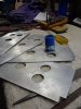
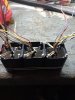
This is what i start with. A section of 1.5" aluminum right angle 6" long. I drill it for tube sockets and tap the holes so that I don't need to use nuts. I tapped 4 holes on the bottom side for the isolation grommets and 4 more for the terminal strips which I build the audio portion on. I built 2 of these modules but I am only working on the one amp right now.

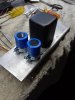
This photo shows the module built and installed in the chassis (chassis by Par metals) . you can see the isolation grommets under the amp module. I made them from rubber wire pass through grommets.

This shows the point to point compact construction of both stages. the tube shields stick out the back panel for ease of service, yet are mounted on their own platform for vibration reduction.

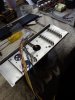
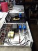
This thread shows the layout of the unit. The transformer is an Edcor, which I had no easy way to mount. My solution was to drop it in a can and epoxy pot it. The can has 4 holes for easy mounting and came out really nice. The main DC will be filtered by F&t electrolytics bypassed with cheap film caps. I've used F&T electrolytic caps before and they seem to work well. (very quiet amp as a result) . I used the cloth wrapped wire because I have about 3 miles of it stripped from old organs, and I think it looks cool.

This is the back panel with the tube access. Im planning to put the output jacks above that area and the inputs to the side. the AC power section will be completely to the opposite side. Thats about all I have to share at this point. I hope my rambling stream of consciousness somewhat resembles the photos... I intend to build a few of these for myself and at least one version using 5691 and 5692 tubes, which I own. If you have any questions or comments, encouragement or otherwise please don't hesitate to chime in.
One of the first preamps I got my hands on was a Dynaco PAS3. I was inexperienced and eager to make this thing sound fantastic, like everyone claimed it would. I yanked the boards, tone controls and almost everything else out, made extensive modifications to nearly every aspect of the preamp, and never did fall in love with it. Moments of sonic euphoria yes, but a undying long term affection, definitely not. I am at a point with it where it works flawlessly and is very low noise. I'm calling it done and the lesson learned is that the PAS, when used as a chassis is an overpriced chassis.
I kept playing with amps, desecrating a few organs and fiddling with their guts is fun for me! Next on the list of projects was a DIY line stage. The plans on DIYaudioprojects.org seemed simple and the cost of entry was lower than what I had into my PAS. It used SRPP 12AU7s which i have plenty of, and once i built it it actually sounded really good to my ears! I made a mental note of the success. This SRPP stage is cheap enough to build, and sounds really good. It has low output impedance and will drive 2 pair of amps. It seemed to me at the time to only be missing one thing. An RIAA phono-stage for all of us REAL audiophiles. (kidding) . I took note also that I may want to use it as part of a larger build someday.
A friend of mine and fellow Audiophile calls me up one day and he has 2 HH Scott LK72s, which he picked up in the early stages of Facebook marketplace. Like within 2 weeks of the launch of the selling feature. It was very shady and there was a huge potential for being ripped off. My pal is a happy go lucky dude and he saves lives for a living and he has lots of good (western) karma so they both showed up in as described condition. both were missing tubes missing knobs broken fuse holders, and priced to reflect all of that. He gave me the uglier of the 2 in exchange for fixing up the better one. The one I ended up with had a problem in the phono-stage! The RIAA feedback network was open, resulting in a higher gain form the broken channel. I spent a lot of time looking for a fault in the good channel, which had lower volume than the faulty one due to the nature of negative feedback. In my process of repairing the amplifier i found it helpful to draw a schematic of the phono-stage and RIAA network separate from the schematic of the entire integrated amp. Once I had rebuilt the PEC (packaged electronic component) which was the cause of the fault, the amp sounded really great. Records had the right sound to them and plenty of punch. HH Scott amps are some of my favorite. At that point the RIAA phono-stage schematic which i drew up on graphing paper got filed in my binder of good schematics. My brain had already made the connection. That HH Scott RIAA stage in front of the SRPP all in one box with switching and volume controls, could possibly be the ULTIMATE PREAMP!!! That is to say I could build it, try it, and it most likely wouldn't sound any worse than what I already have. My mind has been in creative design mode trying to gather ideas of how to lay it all out ever since. Now that it has been brewing in my noggin for a few years it is time to start making chips as they say.
Some of the things i've noted in my head. Your notes may be different and I encourage you to share them.
Organs, portable recording equipment and some military gear sometimes had sensitive tubes mounted on their own isolated sub-chassis. Not all of the tubes, just the ones which were most sensitive to shock and vibration. I'm going to replicate this, because the cost in dollars is low to do so.
HH Scott used aluminum chassis in order to limit electromagnetic irregularities caused by passing current near ferrous metals. A proper preamp chassis should be aluminum.
Stepped attenuators are a topic which I don't have sufficient notes on, but they seem very cool in theory
In reality i would like to be able to stack things on top of a pre. Tubes coming out the top is cool and all but it requires me to have more shelf space, which i don't have. Marantz did a nice job on their model 7 in my opinion putting them in the back, as did McIntosh on the early mono stuff. These things are very nice but unfortunately out of my price range. Out back they are easily rolled or serviced without removing the hood, and I can stack something else on top of the pre.
Ideally the entire AC power supply would be located in a separate chassis and connected via an umbilical cord to the Amplifier section. I'm not going that route as it would substantially increase the cost and complexity of the design. I am however putting all of these components on the other side of an aluminum wall from the audio section.
Dale CMF 60 resistors come in .1% tolerance and are specced to 3 significant figures. I also like how they write the value on the resistor in plain old numbers. I have had only good luck with them. They are expensive but then again so is anything good.
Other members of my local audio club have mentioned also failing to fall in love with a preamp. Several of them are DIY type of guys and we even took a delegation to Burning Amp in SF last year. We had one of the better sounding setups at the show and everyone had a great sounding setup. Between us we have a tremendous body of tools and skill to draw upon.
So I proposed it to the guys in the club like this. If we all go in together on parts and supplies once i have it prototyped and the bugs worked out, I think we can each have one for about $500 in parts. I got 3 or 4 solid yeses from the guys and I intend to take what i have built to the next audio club meeting to show the guys what I have in mind. Basically if you are a member of the Chico audio club I am going to offer to guide you through the construction of your own Tube RIAA preamp! I have a schematic drawn up and a bill of materials nearly complete. I'm waiting on a few parts to arrive in the mail like RCA jacks and switches. I also need to fabricate one panel for the inside which will wall off the power supply section and effectively shield the Audio half from the noise inside. I'm dying to hear how it sounds but I'm not willing to take any shortcuts to get there...
I have decided to name my great work of plagiarism, "The Members Only Riaa preamp" . Ok here are some photos.
This is what i start with. A section of 1.5" aluminum right angle 6" long. I drill it for tube sockets and tap the holes so that I don't need to use nuts. I tapped 4 holes on the bottom side for the isolation grommets and 4 more for the terminal strips which I build the audio portion on. I built 2 of these modules but I am only working on the one amp right now.
This photo shows the module built and installed in the chassis (chassis by Par metals) . you can see the isolation grommets under the amp module. I made them from rubber wire pass through grommets.
This shows the point to point compact construction of both stages. the tube shields stick out the back panel for ease of service, yet are mounted on their own platform for vibration reduction.
This thread shows the layout of the unit. The transformer is an Edcor, which I had no easy way to mount. My solution was to drop it in a can and epoxy pot it. The can has 4 holes for easy mounting and came out really nice. The main DC will be filtered by F&t electrolytics bypassed with cheap film caps. I've used F&T electrolytic caps before and they seem to work well. (very quiet amp as a result) . I used the cloth wrapped wire because I have about 3 miles of it stripped from old organs, and I think it looks cool.
This is the back panel with the tube access. Im planning to put the output jacks above that area and the inputs to the side. the AC power section will be completely to the opposite side. Thats about all I have to share at this point. I hope my rambling stream of consciousness somewhat resembles the photos... I intend to build a few of these for myself and at least one version using 5691 and 5692 tubes, which I own. If you have any questions or comments, encouragement or otherwise please don't hesitate to chime in.