• The move to the new server is done. There are some software and database maintenance updates in process. This has us passing the hat around to help out. We appreciate any donations. Seriously, even a dollar helps. The payment page may be found here - https://www.audiokarma.org/support.html

The Official "Build" thread for the V4 WYN Phono preamplifier

Register to hide this ad
The switch explanations/settings.
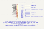
switches.png
Above is the translation of the control socket wiring to the switches. It is recommended that the wires be labelled as shown for wiring to the switches or at least identified in a known way. Note that the internal node names in the circuit (as shown to the left of the socket) are not necessarily the same as the names on the wires.
As can be seen the IP stage 6dB extra gain switch shorts the wires labelled IP6dBR/L together using a double pole switch.
Similarly for the OP stage 9dB gain, where the OP9dBR/L wires are shorted together by a switch.
The warp/stereo/mono switching either shorts the WARPR/L or the MONOR/L to the FILTIPR/L for WARP or MONO or leaves the connection open for STEREO.
Again, a double pole switch or two is needed.
Two are needed if the mono/warp choice is to be made by one switch, then the mono(warp) or stereo choice is to be made by a second switch.
One is needed if the switch is three way, with the central setting being No Connection for STEREO and the other two being MONO or WARP.

There is also a POWER on off switch. It is a DPDT switch. The first pole is for opening or closing the AC line to the power supply (PSW1), and the second is for disabling or enabling the output relay coincidentally with the opening or closing of the AC switch (PSW2). The switches are therefore wired opposite in phase.
When the power is turned on there will be a delay of about 30s until the outputs are enabled.
In addition there is a separate MUTE switch. This is in parallel with PSW2. It is recommended that the mute is activated any time a MM/MC selection or a WARP/MONO/STEREO selection is made.
When the mute is activated the output relay is turned off. If the mute is deactivated the relay will be on after a delay of about 30s.

 
Last edited:
Thank you all,
For me; I'd be interested in getting a better understanding of how the switches are all connected--and switched.
t
 
I'm working with @mkane to build three V4.0 preamps; two for me and one for him. He solders well (@mkane: how many V1 to V3s have you assembled?) and ordered the PCBs then I attend to more pedestrian matters regarding the enclosure, engraving the front and back, selection of switches and doodads to make them look good, input/output jacks, etc. So far we've settled on:

Enclosure: Modushop Galaxy, 3mm front, 330w x 170d x40h, black (1GX347N). It has 1mm thick steel top and bottom. This is the same type of enclosure used in the prototype.
Switches: All are Carling from Antique Electronic Supply aka Tubes and More
  • Power, +6dB gain, +9dB gain: DPDT SKU: P-H541
  • Stereo w/warp filter - Stereo - Mono: DPDT on-off-on SKU: P-H542X
  • Mute: SPDT on-on SKU: P-H540
  • Appearance: I've ordered black "Dress Nuts" and "Toggle Caps" of various colors to see what, if any, look good.
  • Note 1: only part of the full function of the switches for gain and mute will be used but since I wanted to use switches with identical toggles, threaded barrels etc to achieve a consistent look.
  • Note 2: I'd appreciate it if someone reviews these switches to make sure they will work for their intended purposes. I also need to better understand how to hook them up to the pins on the PCB.
Jacks: I'm going to use red and white Neutrik RCA jacks for input and outputs
18VAC Power: Jameco 18VAC wall wart and corresponding panel jack

I still need to decide how to access the DIP load switches mounted to the PCB. My choices so far are to just take off the top but I need to figure out how to fix the four nuts that loosely fit into channels in the enclosure's sides that mate with the screws holding down the top. Alternately, make some kind of removable hatch to cover a hole in the top above the DIP switches. TBD.

Once I get all the jacks and switches I will see how much room there is for engraving and what it will look like. A name for this preamp? My leading contender is "Wyn Palmer Phono Preamp" on the front with "V4.0" on the back somewhere. TBD and open to suggestions.

@mkane has the PCBs from OSHPark and if he wants can provide an update on the Mouser order. Finding alternate parts for those out of stock will likely be a team effort.
 
All of the switches etc. seem fine to me.
Will the DIP switches fit under the board? That way the holes can be on the bottom. The apparent pinout may change, but that's not a big deal.
 
  • Like
Reactions: j!m
All of the switches etc. seem fine to me.
Will the DIP switches fit under the board? That way the holes can be on the bottom. The apparent pinout may change, but that's not a big deal.
Thank you for checking my switch choices. I literally sat down with a diagram of each of those switch types to understand how they'd work in V4.0. I need to read the note on the schematic and shown above to sort out which wire goes were on these switches.

I hadn't thought I could point the DIP switches down, thanks! The vertical constraint is the height of the caps on the PS board and it apparently was very tight in the same Modushop enclosure used for the prototype. But if I separate the preamp board from the PS board I can use different length nylon risers to get the DIP switches just inside the bottom of the enclosure and minimize the ones under the PS to keep the top off the top of the caps. Brilliant!

Related to separating the two segments of the PCB; is there any benefit to putting a grounded, say 1/8" thick piece of aluminum or steel vertically between the separated boards?

Now about that pinout change? Is that just noting that for example DIP position 2 would be DIP position 6 when the switch is pointed down? Or something like that?
 
Thank you for checking my switch choices. I literally sat down with a diagram of each of those switch types to understand how they'd work in V4.0. I need to read the note on the schematic and shown above to sort out which wire goes were on these switches.

I hadn't thought I could point the DIP switches down, thanks! The vertical constraint is the height of the caps on the PS board and it apparently was very tight in the same Modushop enclosure used for the prototype. But if I separate the preamp board from the PS board I can use different length nylon risers to get the DIP switches just inside the bottom of the enclosure and minimize the ones under the PS to keep the top off the top of the caps. Brilliant!

Related to separating the two segments of the PCB; is there any benefit to putting a grounded, say 1/8" thick piece of aluminum or steel vertically between the separated boards?

Now about that pinout change? Is that just noting that for example DIP position 2 would be DIP position 6 when the switch is pointed down? Or something like that?
Yes you can split the boards. You could also find a lower profile switch.
Flipping the dip switch to the bottom is transparent if you keep the pin 1 identifier on the same side (left or right) of the board.
 
And any benefit to a shield between the separated boards? My suspicion is, no, since during your testing V4.0 met your expectations regarding noise were met.
 
And any benefit to a shield between the separated boards? My suspicion is, no, since during your testing V4.0 met your expectations regarding noise were met.
I really can't answer that. It can't hurt.
Make sure that all of the board to board connections are made. No exceptions.
 
Bottom side switches is a brilliant idea.

Case bottom could be engraved with the “map” identifying the switch functions.
 
I'm building three amplifiers. I've assembled three PSUs and one amplifier without big problems.

There is one small error in the BOM. The R66,71,184,185 on line 62 has a quantity of only 2 instead of the needed 4. Correct the quantity when ordering.

I'm using a Modushop Galaxy GX247 230 x 170 x 40 mm. The usable width is 210mm, which fits nicely if you break the PCB splitting the psu from the amplifier and file the remaining 'teeth' flat.
Yes, the psu with the filter caps, which are the tallest components, do fit in the 40mm height. You need to use 5mm standoffs to make it fit.

One snag I've encountered is that I opted for the nice 10mm aluminium front. I've realised now it is quite tricky to get switches with long enough barrel, and a power LED would also be more complicated. I've ordered three 3mm front panels from Modushop as a replacement for the 10mm. Lesson learned.
 
You could possibly counter bore where the switches mount to make the front "thinner" where the switches are. Actually, fairly common practice on many "pro" pieces of equipment. Well, when they HAD switches...

1740584189732.png
 
Yes, this is what I do. I have end mills, metal cutting hole saws and a milling machine, but you can do it with a drill press, and some even just use a really slow speed and Forstner bits. You can recess from the rear, or even the front, as in this example:

GKTIPF-1.jpg
 
Back
Top Bottom