• The move to the new server is done. There are some software and database maintenance updates in process. This has us passing the hat around to help out. We appreciate any donations. Seriously, even a dollar helps. The payment page may be found here - https://www.audiokarma.org/support.html

The Official "Build" thread for the V4 WYN Phono preamplifier

Just information:

I ordered the push button MM/MC switches, sans cap, from Mouser today to take care of the V4.0 builds @mkane and I are working on. I need the switch sooner than the rest of the BOM parts so I can figure out how to make an extension for the push button that is key to the layout I'd like to do. The version with the black cap in the BOM is not in stock at our typical sources and won't be available until May.

The total cost included: 1) the switches, 2) state sales tax, 3) shipping and 4) a pass through of the 10% tariff on Chinese products. I'm not sure if my order will be amended to reflect the additional 10% tariff that went into effect today.
 
  • Like
Reactions: j!m
.... I need the switch sooner than the rest of the BOM parts so I can figure out how to make an extension for the push button that is key to the layout I'd like to do.
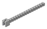
I'm preparing to print something like this, the idea is "cut-to-length": the "tip" of the switch plunger is replicated every 0.118" (factory spec). Or .. the "tip" could be replicated at more logical intervals.

Switch-rod-mod-8.JPG

I don't have a real switch or button to confirm the dimensions are correct though, so someone would have to try it first.

Are you ready to be the tester?
 
You could print the end bit with a #4 screw through hole and then rod of any length could be used.

The other end replicating the switch itself, with a similar hole...

That also allows "S" bends in the rod if required.
 
I'm preparing to print something like this, the idea is "cut-to-length": the "tip" of the switch plunger is replicated every 0.118" (factory spec). Or .. the "tip" could be replicated at more logical intervals.

View attachment 3445750

I don't have a real switch or button to confirm the dimensions are correct though, so someone would have to try it first.

Are you ready to be the tester?

Absolutely! That looks like a great solution. The switches I ordered will be delivered tomorrow so I can take any measurements you'd like and I'll be very happy to give it a go. A couple of things come to mind:
  • I could not find any switches with the round cap so the ones I have coming are cap-less. I am headed to my terrific local "hardware" store to see what I may be able to use as a round cap (easier to drill a hole!). Any suggestions?
  • I have no idea how strong the 3D printing medium is and how long these extension rods can reasonably be. Thoughts?
  • My tentative layout in a Modushop enclosure puts the edge the PCB about 25mm to 30mm from the face of the back panel and with another 5mm or so for the switch travel should work great with your design.
 
Last edited:
Absolutely! That looks like a great solution. The switches I ordered will be delivered tomorrow so I can take any measurements you'd like and I'll be very happy to give it a go. A couple of things come to mind:
  • I could not find any switches with the round cap so the ones I have coming are cap-less. I am headed to my terrific local "hardware" store to see what I may be able to use as a round cap (easier to drill a hole!). Any suggestions?
  • I have no idea how strong the 3D printing medium is and how long these extension rods can reasonably be. Thoughts?
  • My tentative layout in a Modushop enclosure puts the edge the PCB about 25mm to 30mm from the face of the back panel and with another 5mm or so for the switch travel should work great with your design.
Measurements not needed, I got all the dimensions off the manufacturers data sheets. But given hobby level FDM printing, dimensional accuracy isn't guaranteed, and I will have to make adjustments after measuring the 1st prototype:

proto-rod-1.jpg

3D prints can be VERY strong, depending on filaments used, tho I don't think it's necessary for this application. Even the lowest performing filament is up to the task.

Given how small this thing is, and the limited resolutions of FDM printers, it might be best to have made by a commercial printer.

re. MM/MC switch: in my first layouts, MC was pushed in, but Bill might have changed that, so only he can say.
 
I have a resin printer but my experience from a few years ago is even the "ABS-like" resin is brittle, though better than standard resin which is like ribbon candy...

But detail is its specialty.
 
Measurements not needed, I got all the dimensions off the manufacturers data sheets. But given hobby level FDM printing, dimensional accuracy isn't guaranteed, and I will have to make adjustments after measuring the 1st prototype:

View attachment 3445976

3D prints can be VERY strong, depending on filaments used, tho I don't think it's necessary for this application. Even the lowest performing filament is up to the task.

Given how small this thing is, and the limited resolutions of FDM printers, it might be best to have made by a commercial printer.

re. MM/MC switch: in my first layouts, MC was pushed in, but Bill might have changed that, so only he can say.

Outstanding! PM sent.
 
@hirscwi - or anyone who has yet to populate their board - a request, please.

Can you post higher resolution photos of the bare boards? I neglected to follow my normal practice of doing so before populating and am having difficulty finding a resistor position. Once a space is populated the numbers are not visible, and having a good photo of the board is a good cross-check when building up the boards.

My currently "invisible" resistor is R32 - 100R, BOM line 9.

Correction noted in post 55 below.

@AvFan - the board says Push In for MC, out for MM

Thanks!
 
Last edited:
@AvFan - the board says Push In for MC, out for MM

Thank you for the switch info! Once I set the layout in the enclosure I will be able to design the back panel engraving including for the MM/MC switch. @mkane and I are working together on our builds and he has our PCBs. He sent me a photo from some distance but the resolution isn't high enough to be able to zoom in and read the the MM/MC switch info. I'm afraid the photo won't be much help to find your invisible R32 resistor either. Thanks again for the switch info.
 
@hirscwi - or anyone who has yet to populate their board - a request, please.

Can you post higher resolution photos of the bare boards? I neglected to follow my normal practice of doing so before populating and am having difficulty finding a resistor position. Once a space is populated the numbers are not visible, and having a good photo of the board is a good cross-check when building up the boards.

My currently "invisible" resistor is R32 - 100R, BOM line 9.

@AvFan - the board says Push In for MC, out for MM

Thanks!
Sorry, but I don't have any photos of unpopulated board.

R32 is just next to the wallwart input in the power supply section. It's optional 10 ohm resistor used as a ground hum breaker - between signal ground (GDNA) and connection to be used to chassis. This is a typical approach to put 10r resistance between signal ground and chassis but is not required.

R32 is 10 ohm (along with R54, 55, 57, 58, 108, 109, 110, 111. That's how it's listed on the BoM that should be on the dropbox. p/n is 708-RNMF14FTC10R0. If that's not how your BoM is, then we need to track down the error.
 
Some of the discussions over the past few days remind me of a few generic suggestions to be included in the build notes:
  • Take a photo of the PCB prior to stuffing components
  • Have a clear printout of the schematic during the build process.
  • Compare component values to the schematic. That approach is more reliable than the BoM.
  • Generally advisable to verify resistance before soldering in early builds
  • Acquire boards prior to acquiring enclosure or front/rear panels
  • Use a DMM to verify soldering on SMD parts. Look for connection to pads and shorts between legs (especially of ICs and transistors). The DMM can find problems that aren't apparent visually.
These are merely suggestions, purely my opinion, and many experienced builders do not follow them. I'm not seeking an argument on these topics - there are many ways to skin a cat.
 
Thanks for getting me to take a better look, @hirscwi. I see the location now.

Re: the "100 Ohm" value I stated, that was me switching between magnifying lenses and no glasses at all while mis-reading the component bag markings. 10Ohms looked to me without glasses like, you guessed it - 100. So, no problem with the BOM in that regard. However, some parts with many location numbers didn't import into the Mouser cart completely, with only about 5 numbers showing up on the bag and the packing list. I'll add this to your useful suggestions:

* Double-check your BOM against the parts bag and packing list for missing part location numbers (e.g. R109, 110, 111) and add those by hand to both the bag and your packing list.

Because the schematic part numbers do not necessarily flow in order from one portion of the schematic to the other, cross-checking against the schematic will take more time, but is definitely good practice. A lot of what I've been doing lately is repairing old audio gear with no schematics - having one to build from is a luxury.

Builders of this project are likely to be experienced builders who may already follow all of these suggestions, but another practice I use when populating the board is to check each part number off the bag label and the packing list after installing each part. This is particularly helpful when there are a lot of locations for one part, or a large number of parts for a build.
 
Some of the discussions over the past few days remind me of a few generic suggestions to be included in the build notes:
  • Take a photo of the PCB prior to stuffing components
In the Kicad 2D or 3D board rendering, disable "Show thru-hole/SMDSMD parts". That leaves the bare board w/silkscreen. Save the image & pass it around.
 
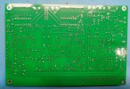
Here are a couple of progress photos. After flux removal from the top and bottom of the board prior to installation of a few of the electrolytic caps. Final flux removal and cleaning after complete board population.

V4TopProgress.jpgV4BottomProgress.jpg
 
Here are a couple of progress photos. After flux removal from the top and bottom of the board prior to installation of a few of the electrolytic caps. Final flux removal and cleaning after complete board population.

View attachment 3447740View attachment 3447741
Looks good! I'm curious how tall the red caps are on the preamp and the black one is on the power supply board. I'm trying to squeeze my V4.0 into a 1U height (40mm) enclosure. And are the red and black caps the ones in the BOM? Thanks!
 
The tallest cap on the main board is 21.3mm - that's the one at the top left corner of the photo. The blue film caps are a smidge taller than the red electrolytics, at 12.7mm off the board. From the bottom of the board to the top of the tallest cap is 23.05mm, so figure your 5mm standoff and some clearance at the top of the cap gives you maybe 30mm.
 
The tallest cap on the main board is 21.3mm - that's the one at the top left corner of the photo. The blue film caps are a smidge taller than the red electrolytics, at 12.7mm off the board. From the bottom of the board to the top of the tallest cap is 23.05mm, so figure your 5mm standoff and some clearance at the top of the cap gives you maybe 30mm.

Thanks! Those measurements will allow me to figure out if I can put the MM/MC switch at the mid-point of the back panel. Close I think.
 
Back
Top Bottom