• The move to the new server is done. There are some software and database maintenance updates in process. This has us passing the hat around to help out. We appreciate any donations. Seriously, even a dollar helps. The payment page may be found here - https://www.audiokarma.org/support.html

The Official "Build" thread for the V4 WYN Phono preamplifier

This doesn't make sense unless there's versioning problem with the files. The schematic and layout match. Schematic has error on C50, which translates to same error on layout.
The schematic was examined three times by various eyes, and none of us spotted it, nor spotted it on the board layout where having the negative terminal of an electrolytic cap go to the positive supply should have rung some bells. It's also odd how one channel is fine, but the other is not when they are supposed to be copies. Noone is attaching blame- it's just one of those things. It happens. Of all the errors that could have happened it is amongst the least consequential, at least in the short term, and is trivially fixed, both at the build level and at the database level.
Just do the capacitor removal/rotation, update the Gerbers and move on...
Oh, and for there to be a layout error there had to be a schematic error as Kicad, the tool, ensures the conformance.
However, actual builders only care about the layout, they don't "see" the schematic. They almost certainly don't examine the schematic, even if both are posted.
Hey, it's not like this is a multi million dollar IC where a small error can be catastrophic. I just don't want unexpected failures and caps blowing up.
 
Last edited:
I'm not trying to assign blame. It's a reasonably complex product and exceptional that there was only a single, small error. My point was to see if we had a versioning problem with the files, because, as you indicate, KiCad keeps schematic and layout in synch.

With regard to builders, I continue to recommend that they keep a schematic in front of them as they build. It's better than using a BoM in my opinion because it eliminates one more potential point of failure. Also as Mike Barney pointed out, looking at the schematic would have focused on the incorrect polarity of C50. I missed that but Mike caught it.
I concur. You seemed to be unnecessarily defensive. **** happens, even when significant efforts are made to find errors, as was the case in this instance.
The Dropbox files have been updated.
 
Can one of you post a copy of the corrected KiCad schematic? Much easier to follow than the original schematic. Thanks.
 
Thanks, Wyn, but I was asking for a copy of the KiCad schematic Bill used to generate the board layout. Doesn't have to be the KiCad file, just a PDF, JPEG, etc.
 
Thanks, Wyn, but I was asking for a copy of the KiCad schematic Bill used to generate the board layout. Doesn't have to be the KiCad file, just a PDF, JPEG, etc.
It is the kicad schematic used to generate the latest layout.
There are two Dropbox files identified in post #103. One is for the Gerbers, one is the Kicad schematic.
 
Oh. I didn't recognize it as such; I'm used to seeing them formatted like this. Thank you for clarifying.

67f0f1c9.jpg
 
This may be duplicate - I haven't looked in the dropbox, but here's a compressed PDF. You can scale it to print on multiple pages ("tiled")
 

Attachments

I've tended to use the Microsoft PDF generator rather than the Kicad one- it's actually easier for me to invoke.
However, if it's problematic I'll use the Kicad one.
 
I’ve put together the PS side of thing and have already hit a snag. One side is fine @ 15.5 vdc. The other side not so much at only 8.07vdc.

Can someone give me a hint what the check?
 
I’ve put together the PS side of thing and have already hit a snag. One side is fine @ 15.5 vdc. The other side not so much at only 8.07vdc.

Can someone give me a hint what the check?

Disconnect the +/-15v from the amplifier board.

PSvoltages.png

Check the voltages at the various points shown above.
The numbers will not be exactly the same, but they should be close.
You may not be able to read the values, so here's a list. Remember that the numbers are approximate.
1. The AC input should be c. 18v. Actually, a bit higher.
The "ring" should be at 0v.
2. The voltage on the two large caps should be c. +/-26v.
3. The voltage at the output of the two pass transistor emitters should be +/- 24-25v.
3. The voltage at the output of the LM317 and LM337 should be +/-18.5v.
4. The output from the LM7815 and LM7915 should be +/-15v.
If reporting voltages, please remember to give the polarity relative to ground.
 
Last edited:
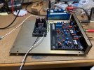
I've completed the assembly of the V4 PCBs, and initial testing indicates no obvious problems. Casework, front panel, switching, etc still need to be done, but it fired up first try. Many thanks to Wyn and everyone involved in the design & testing, and to pfarrell for the PCB!

IMG_1006.jpeg

Below shows 1K signal, top trace is output of V4, bottom trace is output of generator. V4 fed thru inverse RIAA of course.
IMG_1007.jpeg
 
I've completed the assembly of the V4 PCBs, and initial testing indicates no obvious problems. Casework, front panel, switching, etc still need to be done, but it fired up first try. Many thanks to Wyn and everyone involved in the design & testing, and to pfarrell for the PCB!

View attachment 3479623

Below shows 1K signal, top trace is output of V4, bottom trace is output of generator. V4 fed thru inverse RIAA of course.
View attachment 3479624
How was the noise level?
Any sign of intrusive 1/f noise?
 
Some measurements: MM gain: 34.51dB/34.60dB; IP switch gain +6.02/6.02dB; OP switch gain +8.90/8.89dB; all very close to spec. However, I measure MC gain as 50.50/50.55dB, which I though was supposed to 55dB. Possibly I used an incorrect BOM and have an incorrect gain setting resistor? Not really an issue in practice as I can use the IP and OP gain settings to tweak it.
Left to right channel balance was 0.05dB, and frequency response thru my inverse RIAA is within a few hundredths of a dB from 20-20K (I'm guessing the preamp is more accurate than my IRIAA). My power supply output s +15.33/-15.05VDC.
I just listened to the unit with a high output moving coil (on MM setting) and a low output moving coil setup, all seems good. I did find with my SME312 tonearm, I had to connect the tonearm ground to the V4 audio ground to get any signal - possibly a wiring problem in my tonearm.
 
Wyn-
The preamp is dead quiet when lift the tonearm at normal listening levels - just like my V3. An thats with no case - like the photo above.
 
Some measurements: MM gain: 34.51dB/34.60dB; IP switch gain +6.02/6.02dB; OP switch gain +8.90/8.89dB; all very close to spec. However, I measure MC gain as 50.50/50.55dB, which I though was supposed to 55dB. Possibly I used an incorrect BOM and have an incorrect gain setting resistor? Not really an issue in practice as I can use the IP and OP gain settings to tweak it.
Left to right channel balance was 0.05dB, and frequency response thru my inverse RIAA is within a few hundredths of a dB from 20-20K (I'm guessing the preamp is more accurate than my IRIAA). My power supply output s +15.33/-15.05VDC.
I just listened to the unit with a high output moving coil (on MM setting) and a low output moving coil setup, all seems good. I did find with my SME312 tonearm, I had to connect the tonearm ground to the V4 audio ground to get any signal - possibly a wiring problem in my tonearm.
The MC and MM gains are set by two resistors either a 5.1 ohm or a 51 ohm.
Did you switch in the load Rs, and did you have a zero source impedance?
My experience with several channels is that the gain is as advertised, but I'm always open to contrary findings.
All else is good. Thank you.
I can't offer an explanation for the tonearm ground issue.
 
Back
Top Bottom