• The move to the new server is done. There are some software and database maintenance updates in process. This has us passing the hat around to help out. We appreciate any donations. Seriously, even a dollar helps. The payment page may be found here - https://www.audiokarma.org/support.html

The Old Man's First Major Purchase - SX-737 Servicing

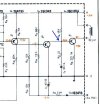
Pin 11 to Q7B is dancing genuinely all over the place from like 2K ohm up to ~5M and down and up and down.
Q7B to C6+ is 22.9 ohm
Q7E to Pin 4 is 216.9 ohm

resoldered all those points plus C5 and C6 and getting the same numbers.
 
Quite the mystery. Let's isolate Q6, what are the DC measurements on the B, C and E?

Are you getting -5.1VDC on the negative terminal of C5?
 
Ok, it sounds highly likely that Q7 or C6 is bad or not installed correctly.

Q5 and Q6 are both in cutoff (as they should be) and should not be affecting Q7.

Does your multimeter have a diode setting? If so, turn the amp OFF and measure voltage drop from 'base to emitter' and 'base to collector'. Positive probe on 'base' in both cases. You should get 0.6 to 0.75V for both junctions.
 
Q7 B to E is 0.639
and B to C is 0.637

C6 is installed correctly by the screen, schematic, and photo of original cap it replaced, but I'll pop it out and test it this morning. Same with Q7, can pull it and put it in my new component tester.
 
ha HA! Pulled C6 and it tested fine and was about to pull one end of R26 to just give that a quick check - had visually inspected all over this board who even knows how many times, but as soon as I put some pressure on one end of R26 it revealed a hairline crack. It broke right in half with a little bit more pressure. Replaced it with a new 68k and the relay clicked right on! I had literally just ordered a new relay about 5 minutes before all this, so now I'm sitting here wondering if I want to solder the old relay back in or just leave it on the bench and replace with the new in a week. Heckyeah. Now may still be more stuff going on here, but this feels like a big win at the moment.
 
Just as I thought, the bias resistor network for Q7 was the issue. Glad you got it.
Thank you so much for your input on this! (And everyone else too) I guess lesson for me here is that transistors and capacitors can be distractions because they're more fiddly and prone to failure and/or incorrect installation, but sometimes an old resistor might just be broken in half.
 
Thank you so much for your input on this! (And everyone else too) I guess lesson for me here is that transistors and capacitors can be distractions because they're more fiddly and prone to failure and/or incorrect installation, but sometimes an old resistor might just be broken in half.
Absolutely. When it can't be anything else, it's usually time to start lifting resistor legs. : )

What clued me in to Q7 bias network is the fact that the Q6 transistor was in cutoff 'turned off' due to its base voltage being less than emitter voltage. In that condition, it cannot conduct from collector to emitter and therefore has no effect on the base of Q7. So Q7 relies only on the resistors to achieve its operating point. If R26 is open, it would make sense that the base is at 0V.
 
ha HA! Pulled C6 and it tested fine and was about to pull one end of R26 to just give that a quick check - had visually inspected all over this board who even knows how many times, but as soon as I put some pressure on one end of R26 it revealed a hairline crack. It broke right in half with a little bit more pressure. Replaced it with a new 68k and the relay clicked right on! I had literally just ordered a new relay about 5 minutes before all this, so now I'm sitting here wondering if I want to solder the old relay back in or just leave it on the bench and replace with the new in a week. Heckyeah. Now may still be more stuff going on here, but this feels like a big win at the moment.
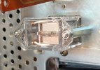
Glad you found it. :rockon: :thumbsup: If it were mine I would put the new relay in, one less thing to bite you in the backside in the future.
 
Glad you found it. :rockon: :thumbsup: If it were mine I would put the new relay in, one less thing to bite you in the backside in the future.
That's the decision I've just come to. It's already out and has some corrosion on a couple of the terminals. Sigh . . . patience, I suppose.
 
That's the decision I've just come to. It's already out and has some corrosion on a couple of the terminals. Sigh . . . patience, I suppose.
Definitely replace the relay. If you do one of these again in the future, note that you can put the diode across the relay terminals instead of the posts on the protection board. That's the way I prefer doing it now. I mount on 30mm M/F 3mm standoffs.
 

Attachments

  • IMG_1276.jpeg
    IMG_1276.jpeg
    151.8 KB · Views: 18
  • IMG_1277.jpeg
    IMG_1277.jpeg
    104.4 KB · Views: 18
Back
Top Bottom