• The move to the new server is done. There are some software and database maintenance updates in process. This has us passing the hat around to help out. We appreciate any donations. Seriously, even a dollar helps. The payment page may be found here - https://www.audiokarma.org/support.html

The Old Man's First Major Purchase - SX-737 Servicing

Hip Priest

New Member
Hey folks. So I've been starting to work on my dad's good old SX-737 - his "first major purchase" of his life. I had been lugging it around for the past couple decades and getting great use out of it, but it started to have the issue of the intermittent relay cutting out which got persistently worse until the thing just ended up just collecting dust for a while. Couldn't ever bear to part with it and know enough about knowing enough that I figured I could take a crack at trying to service it.

So here's where things stood before any work: when it was functioning, everything was working as expected (minus a couple burnt out bulbs on the front panel), but the relay would drop out with the loud "click". Sometimes it would click on and off rapidly several times and, increasingly more often than not, end up just staying off. Often if I let it sit for a while and powered it back on again it would engage, but usually only stay on for ~30 seconds to a minute.

SO I ordered some rebuild kits for the power and protection boards. Went through both of those with minimal troubles. Clearly I should have been more methodical and incremental in my testing along the way - that's a big note to self, but after replacing all the capacitors and transistors in both boards (Power and Protection) I'm getting power but the relay is not engaging at all.

I've been through and tested the values off all the pins (included at the bottom for reference) from this incredibly helpful thread: https://audiokarma.org/forums/threa...-rebuild-on-a-sx-737-done-by-a-newbie.985597/ and have confirmed that everything is coming in right around the expected voltages. I've also confirmed that power is getting to the leads of the relay.

I suspected and checked Q7 on the protection board, but it seems to be functioning as intended.

The other note I've made in working on this is that the Power board around Q3, Q1, and particularly that big R3 resistor looks like it has spent some time being very hot. I tested R3 and its resistance is still giving correct values, but even just powered on and testing a couple minutes, it does get pretty toasty.

I suspect one of my next stops might be to test the actual relay itself?

This is just the start. Going to keep poking around and looking at things both on the boards and in these forums, but any advice, guidance, wisdom, or insights will be greatly appreciated.

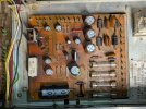
Protection Board
PXL_20260826_192424527.jpg

Power Board
PXL_20260826_192700855.jpg


---Expected Pin Values Reference---
Power Supply
AC

Pin 1, +7.5 VAC
Pin 2, from fuse F1 to pin 12 Protection Board +7.5 VAC out and to the Lamp Assy
Pin 3, to F2, +37 VAC
Pin 4, to F3, +37 VAC
Pin 5, = GND AC
Pin 6, to F4 +35 VAC
Pin 8, +27 VAC
Pin 11, to D3+D4 +27 VAC

DC
Pin 7, unregulated (it can vary) -38 vdc
Pin 9, + to C1, unregulated (it can vary) +35 vdc
Pin 10, - to C2, unregulated (it can vary) -35 vdc
Pin 12, regulated -13 vdc
Pin 13, regulated -13 vdc
Pin 14, regulated + 36 vdc
Pin 15, + 31.5 vdc
Pin 16, + 31.5 vdc
Pin 17, + 24 vdc
Pin 18, = GND DC
Pin 19, regulated + 13.5 vdc
Pin 20, regulated + 13.5 vdc
Pin 21, regulated + 13.5 vdc

Protection Board
Pin 2, -13.3 vdc
Pin 9, relay pulled in, +9 vdc
relay not pulled in +31.5 vdc
Pin 10, +35 vdc
Pin 11, +35 vdc
Pin 12, + 7.5 VAC
 
Register to hide this ad
My first thought is testing the transistors and diodes on the protection board:


Also, It looks like you replaced Q7 with the KSC2690. Are you sure the replacement pinout is correct?

Regarding the resistors on the power supply board, I would at a minimum replace the 180ohm wirewound with a 7.5W or 10W and lift it off the board as well.

I'm sure experts on the 737 will chime in with their tips.
 
Diodes is probably a good next check - the rebuild packs I got came with replacement diodes so I've got some on hand ready to go, but I hadn't bothered with em to this point.
 
Replaced the diodes on the power supply. Two of them were fairly corroded and they were getting weird readings in circuit, but tested okay once I pulled them. Regardless they're replaced with new now. Still not getting the relay to engage but now I'm getting the 35.5v on both pins 9 and 10 on the protection, which isn't quite correct.

Off Q7 in the protection I'm getting:
B 0v
C 35.6v
E 0.005v

which certainly isn't right according to the schematic. Hmmm. Welp, gonna go look at the eclipse and think about my life.
 
On the protection board, take a look at Q1 and Q2. Are they 2SC869 or have they been replaced with something else?
 
You wrote, the ksc1845 is reversed from the SC869s. Did you mean the pin out?

The pinout of the 2SC869 transistor, viewed from left to right with the flat side (the side with the markings) facing you and the pins pointing downwards, is: Emitter, Collector, Base. This corresponds to the classic ECB sequence.

It’s the same pin out on the KSC1845, the classic ECB sequence.

What to you use to identify the correct transistor pin out?
 
Last edited:
I believe 2SC869 is 'B C E' (left to right, looking at the flat face). So the replacement KSC1845 should be mirrored, which they appear to be.

I'd take the following steps:

1. Take a look at the foil side and look for lifted traces, cracks, or loose soldering joints.

2. Test pin 12 for 7.5V AC and pin 2 for -13VDC.

3. If you have a bench power supply, pull the relay from the circuit and put 24VDC across the coil terminals. At this point you might as well replace the relay.
 
Personally, I'd replace the relay as it's an item worth replacing.

If the replacement relay doesn't solve it, it's possible that you have a power amp error causing the relay to remain open.

Check the DC voltages on Q3 and Q4 to ensure you have 20V at collector, 0V at base, and -0.6V at emitter for each transistor. If you don't, it's possible you need to adjust your DC offset.

Check to make sure the collectors of Q1 and Q2 are 20V.

Check that the base of Q5 is slightly higher than the collectors of Q1, Q2, Q3, and Q4. It should read something around 20.5V.
 
I believe 2SC869 is 'B C E' (left to right, looking at the flat face). So the replacement KSC1845 should be mirrored, which they appear to be.

I'd take the following steps:

1. Take a look at the foil side and look for lifted traces, cracks, or loose soldering joints.

2. Test pin 12 for 7.5V AC and pin 2 for -13VDC.

3. If you have a bench power supply, pull the relay from the circuit and put 24VDC across the coil terminals. At this point you might as well replace the relay.
12 is 7.95V AC
2 is -12.69V

and for good measure
9 is 35.42V - I believe this is high for spec
10 is 35.44V
11 is 35.45V

Will pull the relay in a bit here and see if I can get it to click on the bench.
 
Maddeningly, the relay clicks with 24V through it on the bench. Enthusiastic to find something obviously wrong here.
 
I don't see where you have checked the voltages on pins 1 and 3 of the protection board. Those pins watch the DC offset of the power amplifier and should be in the 0-20 mV range. It is possible that everything else is fine and the amplifier section has a high DC offset stopping the relay form engaging.
 
I don't see where you have checked the voltages on pins 1 and 3 of the protection board. Those pins watch the DC offset of the power amplifier and should be in the 0-20 mV range. It is possible that everything else is fine and the amplifier section has a high DC offset stopping the relay form engaging.
Pin 1 is 0.014V and Pin 3 is 0.009V

That's a good thought about the amp board. My rebuild kit only had parts for the power and protection so I hadn't started looking into the amp yet. I had presumed - seemingly incorrectly that the relay was a bit of a brick wall that kept those two boards isolated from everything downstream, but that makes sense about the Amp's offset being a potential player there.

In service of all this I've got a transistor tester that just arrived in the mail and I'm going to build a Dim Bulb Tester this weekend to continue trying to puzzle through this project.
 
In service of all this I've got a transistor tester that just arrived in the mail and I'm going to build a Dim Bulb Tester this weekend to continue trying to puzzle through this project.

That should always be the first step. What I really miss at the beginning was any word about the use of a DBT and the results. Second, use a transistor tester like the LCR-T4 Mega328 on EVERY replaced transistor to identify the correct pin out?
Third. Your posted voltages appear more like the “should be” and not like the measured one on your unit. We need to know the real situation to get a picture.

Before you proceed, I strongly recommend reading this thread in its entirety and finding out what you should avoid if you expect help.
https://audiokarma.org/forums/threa...o-relay-click-lights-on.1097512/post-18075181

In the end, it was the longest thread about restoring an SX-737—with only a few genuine faults, but all the more self-inflicted problems.
 
I don't see where you have checked the voltages on pins 1 and 3 of the protection board. Those pins watch the DC offset of the power amplifier and should be in the 0-20 mV range. It is possible that everything else is fine and the amplifier section has a high DC offset stopping the relay form engaging.
While this is a good check, I would go further as I mentioned above in post #11. This verifies that the transistors and diodes on the protection board are working as intended. Your DC offset voltages could be fine but there could be an issue with the differential pair (Q3, Q4).

If you are measuring 35V at the collector of Q7, it sounds like something is turning on Q5. That would most likely be the current drawn through D5, D6 or D7.
Oh thanks! I had missed you post #11 somehow.

Okay Q3 and Q4 values (respectively) are:
C 20.05V and 20.06V
B -0.005V and -0.004V
E -0.612V and -0.611V

Q1 and Q2 are both getting 20.18V on the Collectors
0.018V at the Bases
and the Emitters are dancing up and down from -1V to 0.02V

And Q5 has 20.52V at the Base
-1 at the Collector
and 17.66 at the Emitter
Q3 and Q4 sound good.

Q1 and Q2 seem reasonable, though the emitter dancing could be something. Let's put a pin in that.

Q5 values are right where they should be.

I think Q7 or the reservoir capacitor C6 might be the culprit.

Perform the following measurements with the amp turned off:
1. Resistance from Pin 11 to Q7 base. Should be 68k ohm.
2. Resistance from Q7 base to C6 positive terminal. Should be 22 ohm.
3. Resistance from Q7 emitter to Pin 4. Should be 220 ohm.

It's possible that when you replaced Q7, you didn't flow enough solder onto the base and emitter pads that connect directly to the biasing resistors.

Also take a look at the soldering on C5 and ensure that's in good shape.
 
Back
Top Bottom