• The move to the new server is done. There are some software and database maintenance updates in process. This has us passing the hat around to help out. We appreciate any donations. Seriously, even a dollar helps. The payment page may be found here - https://www.audiokarma.org/support.html

There's the other GUANZO thread.

Rob DeFries

Active Member
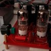
Yesterday I received my copy of the Guanzo version 2.2
I've read a lot anout it already, but I haven't seen many solutions to many answers.
I did find a schematic, but than again a schematic without power- and heater supply.
Atleast now I know where to look if things go wrong.
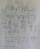
Here is the somewhat clumsy but readable schematic.
20160913_122607-1.jpg
There are some thing wrong with the board, so I rather check everything first, before I hook up a transformer which produces 238 Volts at idle.

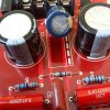
The filament is the wrong way around. Under the 2200uF/16V cap are 3 small holes. These holes connect to ground on the bottom. But that now has the + of the filament on it.
2016-09-13 11.05.23.jpg
The correct way to solve this is to put the cap in the other way, but also the rectifier needs to be reversed. For both the cap and rectifier bridge counts: the + has to go into the - hole.
 
Register to hide this ad
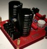
Things reversed and upgraded. Dunno about the 200V caps, but idling at 238V I'd use a bit higher of a cap voltage. 450 is over the top, but I had them handy.....

2016-09-13 13.49.28.jpg
 
The voltage of the power supply is higher than the 170V. No wonder, as we've got 235V coming out of the wall sockets.
The filament rectifier still gets warm and voltage is too high, i.e. 7.7V.
That's above the design max of 6.9V. The easiest way is to add a series resistor. I want to drop 1.4V on the 600mA heater current, which is 1.4/.6 = 2.3333, so a 2.2 ohm will do. 1.4 x .6 = 1.04W. I'll have a 2 W handy, so that's what's going on the + leg of the cap, other end into the board, where the cap lead came from.
 
Since I expected the transformer to idle at 235V, I was surprised to see a massif 295V at the caps. (Idle)
Under load there's still 227V at the anode resistors. I do think it's better to use higher voltage caps than the standard ones. They say Rubicon, but can we trust that? They put fake transistors up for sale too....
For sure it wouldn't be the first assembled amp from China to explode......
 
Nice work!

Does it sound as nice as you expected/hoped for?

It sounds very much ok. Loads of clarity, definition and placing. It only get's better. In standard trim. No mods so far.

Can't listen too long, filament voltage is too high. First have to get that right.
 
The 6n2p is more like the 12ax7. The heaters can only be used with 6.3V since they are parallel and have no "midtap" on pin9. Instead, on pin 9 there is a screen between the two triodes, which has to be grounded. A good way to seperate channels.
Russian NOS (1969)

Image39.gif
 
I used a 2R7 2watt resistor in series with the filament voltage. It made the voltage drop to 6.6V which I think is adequate. I guess the current drawn from both heaters is more likely to be 400mA than the 600 mA I read somewhere.
The provision for LED's comes in handy if you need an on/off indicator. Simply solder a LED with leads in the two open connections in the middle of the tubeholder. Might drop the filament a bit more.
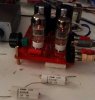
Here's a before and after pic.

20160913_145452-1.jpg 20160914_152427-1.jpg
 
I also wanted to try other coupling caps. For projects I did years ago, I had some NOS TRW caps laying around.
.66uF/400V is a nice first replacement for the .47uF that was used. Instant bass back to normal level. But it took some clarity too.
2016-09-15 10.42.48.jpg
I've seen posts of people using caps of 2.2uF. I think that's over the top, and it can cause some nice motorboating oscillation.
.56 gave me back my bass. You can go up to 1uF if you want, but it hasn't got much use, imo.

The Guanzo is a real pain to mod. Desoldering is difficult, the holes are small, double sided with metal bushing inside. Me no like.
If you want to get the solder out of the holes, put a thick cloth on the bench, heat up the solder in the hole and than bang the board, in one go, on the cloth. Mostly all the solder will drop out.
 
Last edited:
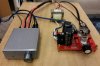
This is more or less my situation.
20160914_164455-1.jpg

If you want the original file, just ask. The original is much easier to read.
I'm off, listening again.
 
I don't really understand the logic behind this design.
1) The input impedance is only 10k. Why? One of the advantages of valves is that the input impedance is easy to get nice and high.
2) The output impedance is variable and goes up to 12.5k (or probably a bit more). Using two gain stages and negative means the output impedance could be lower, but the advantages have been somewhat lost by simply having an attenuator at the output.

I think the performance would be improved by throwing away everything except the 50k pot at the output. The input impedance would be higher, the output impedance would be the same, the noise would be lower and the distortion non-existent. Plus you would save money on your electricity bills.
Or, if you need the voltage gain, make a circuit without PCB and make it work better.
 
I don't really understand the logic behind this design.
1) The input impedance is only 10k. Why? One of the advantages of valves is that the input impedance is easy to get nice and high.
2) The output impedance is variable and goes up to 12.5k (or probably a bit more). Using two gain stages and negative means the output impedance could be lower, but the advantages have been somewhat lost by simply having an attenuator at the output.

I think the performance would be improved by throwing away everything except the 50k pot at the output. The input impedance would be higher, the output impedance would be the same, the noise would be lower and the distortion non-existent. Plus you would save money on your electricity bills.
Or, if you need the voltage gain, make a circuit without PCB and make it work better.
Agreed on everything. Just bought it to see what is was all about. Everybody raving of the sound quality etc.
It does sound good. But it's a strange design indeed. I was planning to move the pot to the input and maybe even inbetween the stages.
But the board just isn't made for mods.
I've got this set up, it works ok, sounds good, but if I hook up my Luxman L-1A, it'll blow the whole setup away.

Still, for under $ 75.00 it's a fun thing to own.
I wasn't looking for high end. Just some fun.
 
Agreed on everything. Just bought it to see what is was all about. Everybody raving of the sound quality etc.
It does sound good. But it's a strange design indeed. I was planning to move the pot to the input and maybe even inbetween the stages.
But the board just isn't made for mods.
I've got this set up, it works ok, sounds good, but if I hook up my Luxman L-1A, it'll blow the whole setup away.

Still, for under $ 75.00 it's a fun thing to own.
I wasn't looking for high end. Just some fun.
Ok, that makes sense. I was pondering what I would do to improve it and thought about putting the volume control between the stages (as a conventional potential divider) but of course the global feedback would try to maintain the same gain regardless of the pot setting, so that's not great.
Putting the pot before the gain stages would mean the circuit is operating at a much lower signal level so the distortion would be much lower, but the signal/noise ratio would be degraded. I suppose it's a toss-up which is the better trade-off.
Anyway, have fun experimenting and get back to us if you come up with anything interesting.
 
Back
Top Bottom