• The move to the new server is done. There are some software and database maintenance updates in process. This has us passing the hat around to help out. We appreciate any donations. Seriously, even a dollar helps. The payment page may be found here - https://www.audiokarma.org/support.html

Time to fix this Harman Kardon hk570i Edit: FIXED

Johnny_Law

o.O
Subscriber
Edit: FIXED, see post #9. Was colder solder joints on the volume pot! o_O

Here we go, another of my restoration projects, which usually involves 95% me beating my head against the wall and 5% actual progress. WOO :whip:

THIS one is a Harman Kardon hk570i. I searched a bunch and didn't find many past project threads about them, so here we go.

IMG_20181125_094113.jpg

The problem is that the right channel is pegged to max volume. The left channel seems to work properly, but at times seems distorted.

Also, it only has done this once, but one time, it was shorting out every 5 seconds or so, causing the DBT to burn bright. Then it would behave, then would happen again, over and over. But I haven't been able to reproduce it.

Here's the bulb under normal operation ... a bit too bright.
IMG_20181125_094119.jpg

Diagnosis done thus far:
  • Listened via headphones. BAD RIGHT CHANNEL, MAX VOLUME ALWAYS
  • Played via TAPE OUT through my garage receiver. BOTH CHANNELS WORKED PROPERLY
  • Deoxited pots & switches as well as I could without invasive surgery. STILL THE SAME
  • Removed & tested output transistors (2SA1146/2SC2706). TESTED GOOD (no shorts using the diode function of my multimeter ... but I am still suspicious)
  • (Note - this same output pair is used in the Yamaha M70 amp which is neat)
IMG_20181125_094206.jpg
  • POWER SUPPLY
  • Checked power supply output voltage. MEASURED +/- ~24.5 VDC WHICH IS LOW COMPARED TO THE REFERENCE VOLTAGE (+/- ~42.5 VDC) RAILS, BUT THIS IS THROUGH THE DBT - SO PROBABLY OK (?)
  • Note, the DBT is only outputting around 88 VAC ...
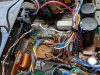
Here's the power supply, and you can see the blue / red wires which take the rail voltage to the amplifier:

IMG_20181125_094140.jpg

So I think I've narrowed the problem down to something in the tone controls or amplifier. Next step is to go through the reference voltages from the service manual and see where I find something funny.

Some of the transistors are in these brackets - I'm assuming to keep them all at the same temp.
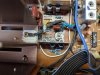
IMG_20181125_094448.jpg

Onwards! :deal:
 
Last edited:
Register to hide this ad
Measured the voltages on all of the other 24 transistors in the power amp, and other than being 20V down on the rails because of the DBT, it all looks pretty good, and the same from one channel to the other. Although not precisely what's in the manual, the values are all the correct polarity and the same order of magnitude as the reference numbers in the manual.

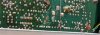
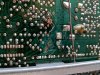
Note: The soldering looking disgusting ... surprised if it came this way from the factory.

Moving upstream ... next are the tone control & volume boards.
 
Something weird with all the hk--- receivers I've had all keep the DBT pretty bright even when working correct. Good luck with it, sounds pretty tough.
 
Hmm, I wonder if these values are OK. These are the main output transistors - B and C seem OK. The emitters though ... they differ from the reference numbers, although they all seem to differ in the same way, it's not just one channel. So although interesting, it doesn't seem to indicate that one channel's transistors are bad. (Right?)

Power Amplifier Output Transistor Emitter Values (all were bouncing up and down within ~10mV):
  • Q428 E: ~ 0.18V (0.022V)
  • Q426 E: ~ 0.15V (-0.05V)
  • Q425 E: ~ 0.10V (-0.05V)
  • Q427 E: ~ 0.14V (0.022V)
Edit: Yeah, took some more pics. Not sure if it came this way from the factory? There is exposed copper in a variety of places as well as scratch marks etc. Left these big so you can zoom in. Note there are a bunch of possible cold solder issues ... I already re-flowed most everything in the amp section, but need to go through the rest of it.

The one section you zoomed in on:

IMG_20181125_181924.jpg
 
Last edited:
That cap is original, they did that a lot. Not sure on the diodes but maybe.

Thanks, I may look for them in the circuit diagram if they lead to confusion ... I did notice the service manual's circuit diagram differs a bit from what's in place. For example, the manual shows 100ohm resistors between various emitters in the power amp and the negative rail, but those resistors don't exist in this unit. The emitters are connected directly to the negative rail.
 
I realized that it might be easier to just follow the A/C signal back through the amp on the bad channel, and see where it starts.

With AUX selected and volume at 0, that's impossible ... but if I switch over to FM, the right channel is immediately blasting through the headphones. At that point, the Q425 & Q427 emitters go wild with something like 5-8 VAC. It seems to me that if I trace this backwards along the signal path, comparing to the left channel the whole time, it may be an easy way to track down the cause.
 
FIXED! I used the above method, where instead of AUX input and 0 volume, I set it to FM input where the right channel was pegged to the max regardless of volume.

I measured AC voltage at the base of Q403 and Q404. The left channel was at 0.03 VAC, and the right channel was at 0.3 VAC! Clearly the problem was upstream of the amp.

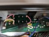
So I investigated the upstream boards (tone control, volume, etc.). I found some very suspect solder joints on the volume pot connections ... AND a random piece of metal bridging the input and output of one channel! LOL! Ding ding ding! Re-soldered the volume pot and we're back in business. Somehow deleted my pic with the bridge in place ... and the final solder pic. But took pics of before / after (I went one more round and filled each solder joint with new solder).

Before:

IMG_20181126_181003.jpg

After(ish):

IMG_20181126_181536.jpg

Here's how bright the bulb is when it's working correctly ... @ivandezande was right, brighter than other stuff I've had on the bench!

IMG_20181126_181403.jpg

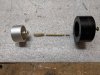
OK ... now for a tragedy. I need a new tuner knob shaft! Here's what this one looks like w/ rough dimensions. If anyone has one I'd love to talk, or any ideas on how to make one, I'm all ears. Anyone with a lathe in their garage feel like helping me out??? :D *cough* Jason @hi*ball *cough* :bowdown: (Threaded length should really be longer, maybe like 25mm, since the part with the nut on it had broken off and was MIA.)

u9vm8V2 - Imgur.jpg
 
Last edited:
How in the sam hell did you break that?

tenor.gif
 
Back
Top Bottom