• Please note that Audiokarma will be offline briefly for updates early on Monday morning, September 28th.

TL072CP lifespan (apt holman preamp)

sae-7125

Super Member
anyone happen to know if the tl072cp has a particular service lifespan out in the wild? currently have an apt holman preamp exhibiting some rather odd tone control and bass mode amplitude+phase issues when comparing left vs right channel output (tone generator as source). preamp was recapped recently but is now becoming a repeat offender in regards to bench repair cycle. pots and relay function seem to be ok, not creating issues. the gremlin is frequency reactive and consistent/stable/repeatable. no intermittent aspect to this circuit issue.

testing a mod for the ever popular relay issue, it has improved relay activation consistency.

also, has anyone bumped into a clean/clear/zoom friendly schematic? the micro dot tattoo on the chassis bottom cover some bald spots, on this particular unit.
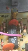
apt chips.jpg
was there a sale on these chips back in the late 70s, several used throughout the preamp system.
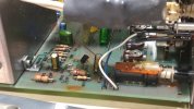
relay-1.jpg
relay circuit with the shorting jumper mod, used to combat the popular relay issue.
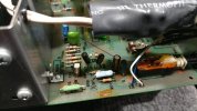
relay-2.jpg
i didnt like the jumper approach, did this instead (220r 2w resistor). the 2.2k mod is for thermal reduction (feeds red LED).
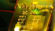
relay-3.jpg
obviously a 24v relay, wonder why the circuit design/engineering chokes it down to 12v? (activation circuit voltage before resistor mod installed)
relay-4.jpg
other side of the relay, basic info.

interesting to note, the 24v unregulated measures 20-21.5v which is sufficient to latch a 24v relay (120v mains applied). and yet there is a glaring restriction caused by a voltage drop across r90 (820r originally installed) which has a drop of around 10-11v when circuit activates after the ~4s delay. this mod adjusts it to 4-5v drop and the relay functions normally once again. using a 2w flameproof resistor is overkill but thats not a bad thing, especially when there is a bag of them sitting nearby.
 
Register to hide this ad
I got my Apt in 2000 w/a dead channel. 1/2 of the balance op amp had gone inop. Replaced it, continued to work fine with other originals until I replaced them all during 2019 overhaul.

Hi-res schematic attached below. It has my own markups noted, as compared to actual board.

You're overlooking part of the circuit.

R90 does not "choke" the relay. It is paralleled by the surge/delay circuit (Q19/C67/R91).

C67 is initially discharged. When Q18 turns on after power-up delay, Q19 is on, shorting across R90, allowing full voltage & current to the relay for positive armature pull-down.

When C67 charges up (@ 0.3 sec), it shuts Q19 off, putting R90 in-circuit, reducing current thru the relay to "hold" value only (it takes more current to activate a relay than it does to KEEP it activated).

This illustrates the surge action. Green trace is voltage across the relay (19v, 10.85 hold), Purple is voltage across R90 (stock 820), Yellow is current thru the relay (26mA, 14mA hold):
Apt-relay-surge-820.jpg

And with R90 reduced to your 220:
Apt-Mute-Surge-220.jpg

As you can see, reducing R90 does not affect the surge current/voltage, only the "hold" values.

The LED/resistor draw 15-20mA from the -24v rail, has negligible effect on the relay circuit.

It seems yout power transformer (with only 20-21v out) may be an issue.
 

Attachments

I've run into a dead op amp or two that failed for no obvious reason, and a simple like for like replacement fixed the problem. Sometimes things just go bad, especially when they are decades old.
 
Yah, I already have that data sheet, and some others that can be more informative.

In another IDEC data sheet it specifies: "Minimum Operating Voltage at 20ºC - 80% of rated voltage".

80% of 24v is 19.2v. The Apt mute circuit is already pushing that limit at 19.6-20v.

If your power transformer is really only putting out 20v, the relay is only getting 16.5-17v, well below the spec.That's why I question your power supply.

The limited voltage may be affecting other circuits as well: eg. the 7818 positive regulator has a 2v drop-out. With only 20v in, asking for 18v out is on the ragged edge of not functioning properly, which might be affecting your tone circuits.

OTOH, are you saying that with R90=820 ohms the relay does NOT operate, but with R90=220 ohms it DOES operate?

If so, that suggests the Q19 surge circuit is not functioning. Q19 is a 2SC1345, known to go bad w/age, might be worth investigating.
 
OTOH, are you saying that with R90=820 ohms the relay does NOT operate, but with R90=220 ohms it DOES operate?
correct, something in the circuit seems far more functional with the resistor mod. the initial red flag was seeing the voltage drop across r90 although no idea if there is a current/amperage restriction that would starve the relay.

if i remember correct;y q17/18/19 were replaced with overkill components (wattage handling) especially after undoing the staple/jumper mod which required activating mute circuit on system power up first. after powered on then clicking mute off and the relay would pull in as expected.

should have a fresh batch of chips inbound sooner or later but the results of the resistor mod seemed interesting enough to post online.

a pioneer elite c-91 has occupied the spotlight (rats nest and all) after the apt holman and now a thermally self destructive designed elite surround receiver is under observation to determine which smt/smd component is out of tolerance causing ~60mv dc offset on a front channel with occasional static noise after the system warms up (sometimes).

its amazing how an 85c environment reduces component life especially when some of those components are rated for 85c (usually 1000 hours or less, electrolytic caps). in regards to the pioneer elite fireball/parts cooker multichannel receiver referenced above.

i wonder if the apt holman preamp txf reaches 24v unregulated if the mains are above 120vac? unless its a tired txf that has adjusted its turns ratio over the decades. at least its not an open primary like a kenwood monoblock (L-07M or something) from years past.
 
anyone happen to know if the tl072cp has a particular service lifespan out in the wild? currently have an apt holman preamp exhibiting some rather odd tone control and bass mode amplitude+phase issues when comparing left vs right channel output (tone generator as source). preamp was recapped recently but is now becoming a repeat offender in regards to bench repair cycle. pots and relay function seem to be ok, not creating issues. the gremlin is frequency reactive and consistent/stable/repeatable. no intermittent aspect to this circuit issue.

testing a mod for the ever popular relay issue, it has improved relay activation consistency.

also, has anyone bumped into a clean/clear/zoom friendly schematic? the micro dot tattoo on the chassis bottom cover some bald spots, on this particular unit.

View attachment 3016379
was there a sale on these chips back in the late 70s, several used throughout the preamp system.

View attachment 3016380
relay circuit with the shorting jumper mod, used to combat the popular relay issue.

View attachment 3016381
i didnt like the jumper approach, did this instead (220r 2w resistor). the 2.2k mod is for thermal reduction (feeds red LED).

View attachment 3016382
obviously a 24v relay, wonder why the circuit design/engineering chokes it down to 12v? (activation circuit voltage before resistor mod installed)

View attachment 3016383
other side of the relay, basic info.

interesting to note, the 24v unregulated measures 20-21.5v which is sufficient to latch a 24v relay (120v mains applied). and yet there is a glaring restriction caused by a voltage drop across r90 (820r originally installed) which has a drop of around 10-11v when circuit activates after the ~4s delay. this mod adjusts it to 4-5v drop and the relay functions normally once again. using a 2w flameproof resistor is overkill but thats not a bad thing, especially when there is a bag of them sitting nearby.


I used to work on quite a few of these. Most of the time we would replace the TL072s with a more modern part but there are tons of them in the preamp. Can be time consuming to replace them all.
 
correct, something in the circuit seems far more functional with the resistor mod. the initial red flag was seeing the voltage drop across r90 although no idea if there is a current/amperage restriction that would starve the relay.
Yes, but if you measure R90 AFTER it's all settled in, you WILL see a voltage drop. This is a transient situation, the Q19 surge circuit only takes 2-300 milliseconds to function, during which R90 is bypassed. It needs to be measured WHILE it's happening to see the effect (as in my simulation graphs above).
if i remember correct;y q17/18/19 were replaced with overkill components (wattage handling) especially after undoing the staple/jumper mod which required activating mute circuit on system power up first. after powered on then clicking mute off and the relay would pull in as expected.
For sure Q17 & Q19 are not original, but there's no need for "overkill". The original parts are more than adequate to handle the loads, by a factor of 2x or more.

Q17 and Q19 are both 2SC1345 NPN, well known to deteriorate or fail with age. One failed in my own Apt signal circuit and had to be replaced.

And there's nothing "special" about the mute transistors. Any good general purpose NPN or PNP will work, so long as they can handle at least 24v & 25mA. I helped another a couple of years ago with a bad mute. His Q17 was in the last stages of functionality. Replaced it with a BC550 and now his mute works fine! Do you know what transistors are in there now?

The factory mute circuit works just fine (as long as all the components are correct, functional and in-spec), there are plenty of Apts out there still running the factory circuit (my own included).

I still think you should chase down the transformer shortfall first. 20-21 volts may be problematic all-round in the future, particularly if the "chips" you're moving to draw more power than the TL072s.
 
i replaced the 5 TL072 chips on the switch board, output amplitude issue did not improve. if anything something is worse now. toggling any of the switches (not the buttons) causes loud popping sound (with or without signal) and speaker cone travel seems to indicate a rather aggressive dc component with slow discharge rate. the opa2134's would be next although there may be some other gremlin in the circuit(s) that is being overlooked.

after exercising the switches and lightly wiggling some transistors, looking for cracked solder joints or thermal reactivity, left channel (typically louder than right hence the issue) expired and no more signal passing through. just low level noise floor indicating some type of electronic activity. the dc click/pop loudness from the switches was dependent on volume knob position vs at zero/silent volume setting.

the headache continues.

Do you know what transistors are in there now?
good question, pardon my obscenely slow reply. cant find any informative photos in my tech archive. might have been something like ksa1013 (pnp) and ksc2316 (npn) since they both have a heat dissipation rating closer to 1w. it would appear that the 0.5w standard package transistors will be sufficient.
 
replaced the other 5 chips (opa2134pa bb) and no improvement. so... my initial evaluation about this being an "aged" chip issue was for naught. interrogating transistors will be the next activity even though the owner has a financial limit for repairs i.e. potential doorstop project soon to be recycled. for some owners of vintage gear it is desirable to have resale value after repairs and updates are taken care of, this is logical.

the kobayashi maru testing continues.

bass mode seems to have no sonic effect, turning down bass (tone) control almost acts like a volume control for all frequencies, not just bass, on the right/good channel. left channel is somewhat functional although at an order of magnitude less than the right i.e. 40mv sine 500hz right results in 3.6mv 500hz left (no tone active). perhaps something simple like an incorrect decoupling cap or defective poly cap. if only the schematic was readable by normal humans instead of people who have microscopes for eyes. although a pcb trace layout would be nice, similar to what major manufacturers have in their service manuals.
 
I have a Holman pre that I bought as a wreck. It needed quite a few things done and one channel was dead. I took a chance and replaced all the electrolytics which restored the dead channel. It worked great for a while then became intermittently noisy. I checked all the transistors which were all OK. After a time, I shipped it to AudioProz. It came back with two of the four IC's replaced. Replacements were the same type as what was inside from the start. No issues since except the input selector switch needs frequent attention.

For some reason, it did not occur to me that an IC was to blame for the noise I was hearing. I was too focused on transistors and not semiconductors in general.

I came across a 2nd Holman Pre not long after, also with a dead channel. Replacement of all electrolytics cured it but did not become noisy as the first had done.

It seemed to me that life expectancy of those IC's can vary from piece to piece.
 
a quick and potentially final update, after cleaning up a few potential solder bridges (pcb trace spacing not good, holman could have done far better) and realizing q16 was backwards (base emitter swapped, no component harm) the issue of minimal tone control sonic changes for the right channel is now repaired. music testing seemed ok performance but tone generator frequency sweep is revealing more than a few age/design issues.

i really should stop looking for gremlins when a system is fully functional to factory spec, or close to it anyway. so... final analysis, no chip issues but the preamp had some sonic clarity/imaging improvements after the ic updates. all the pots sound better after the usual cleaning and the mute relay mod continues to perform without issue.

another one out the door. and now the wide world of oracle turn tables, alexandria 1st version mark 1 plus no accurate schematics (par for the vintage repair course). at least the phase linear 4000 s1 preamp turned out decent, it will keep the model 700 s2 amp company out in the showroom.

pl-4000.jpg
phase linear preamp

orc-1.jpg
oracle top and platter.

orc-2.jpg
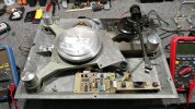
alexandria without its top+cover, oh how scandalous. please ignore the suspension tension mods, for belt alignment motor spin testing.
 
...toggling any of the switches (not the buttons) causes loud popping sound (with or without signal) and speaker cone travel seems to indicate a rather aggressive dc component with slow discharge rate.

.... the dc click/pop loudness from the switches was dependent on volume knob position vs at zero/silent volume setting.
Did you ever find out what was causing this issue? I find myself in the same boat.

I just finished rebuilding an Apt preamp I acquired almost twenty years ago as a parts unit but decided to keep intact and "one day" fix up. "One day" turned out to be the last two months after many years of periodically taking it out, putting it on the bench, discovering something else someone (not me!) butchered on it, then putting it back in storage.

I replaced the relay, every single resistor, electrolytic capacitor, diode, bridge rectifier, voltage regulator, op-amp and push button switch on the dang thing along with almost every transistor. Cleaned up all the solder points, did the mod that uses a flexible wire harness and push on connectors, added bypass caps to the op-amps that had none and cleaned all flux off the boards.

And it works! Except for this damn loud pop whenever any of the toggle switches is thrown. Like you, the loudness is dependent on the volume control setting (no pop when turned all the way down, and increasing in loudness with increase in volume setting). The fact the volume control affects the loudness of it means (I think) the issue is before the volume control.

I've poured over the schematics, all three PCB's, examined every solder joint, semiconductor orientation, double checked all cap and resistor value and I just cannot explain this. HELP! Somebody! LOL o_O
 
Last edited:
Did you ever find out what was causing this issue? I find myself in the same boat.
q16 seemed to have cleared things up, as i had stated in an earlier post. the popping dc issue became worse after most of the ic's were replaced (stronger/healthier chips equals louder gremlin). after that i started to inspect if every transistor was correct (pnp or npn vs schematic and pcb silkscreen e-b-c). it is easy for solder shorts to crop up especially if sloppy soldering technique has been inflicted upon the circuit board. if you are cleaning up a previous owner/repair mess it can be an uphill battle.

almost every transistor.
might be a good starting point i.e. no stone left unturned.

if nte transistors were used to repair or update the preamp, good luck. verify power supply is fully functional, follow the cord to the board is one way of starting at the beginning for any electronics diagnostic work. since popping is volume dependent it is likely something upstream as suspected. another issue with new transistors is unless they are tested prior to installing there will always be the possibility of manufacturer error like a pnp with an npn part number silkscreened on it (been there done that, the little beastie is hanging off a breadtie on a nail above the tech bench).

at least its a small preamp easy to disassemble vs some of the monster pioneer/marantz/sansui receivers some of us have dealt with. the pioneer sx-1980 weighs in at 78 pounds or a marantz 2500 at 60 pounds or a bose 1801 at around 84 pounds (power amp only).


https://www.hifiengine.com/manual_library/marantz/2500.shtml


*i seem to be highjacking and url bombing my own thread, not a good habbit.
 
q16 seemed to have cleared things up, as i had stated in an earlier post. the popping dc issue became worse after most of the ic's were replaced (stronger/healthier chips equals louder gremlin). after that i started to inspect if every transistor was correct (pnp or npn vs schematic and pcb silkscreen e-b-c). it is easy for solder shorts to crop up especially if sloppy soldering technique has been inflicted upon the circuit board. if you are cleaning up a previous owner/repair mess it can be an uphill battle.


might be a good starting point i.e. no stone left unturned.

if nte transistors were used to repair or update the preamp, good luck.
No NTE. Only onsemi, Central Semiconductor, and Interfet. All from Mouser. And all from "cut tape" strip leftovers from a previous Apt preamp project that saw me also do a lot of wholesale semiconductor changes with no issues.

verify power supply is fully functional, follow the cord to the board is one way of starting at the beginning for any electronics diagnostic work. since popping is volume dependent it is likely something upstream as suspected.
Done. All voltages as should be. I even added a polarized AC cord to the Apt after measuring for lowest AC on the chassis as a safety measure.

another issue with new transistors is unless they are tested prior to installing there will always be the possibility of manufacturer error like a pnp with an npn part number silkscreened on it (been there done that, the little beastie is hanging off a breadtie on a nail above the tech bench).
That's always possible. Even someone like onsemi might pop in a bad or mislabeled sample among the good ones.
at least its a small preamp easy to disassemble vs some of the monster pioneer/marantz/sansui receivers some of us have dealt with. the pioneer sx-1980 weighs in at 78 pounds or a marantz 2500 at 60 pounds or a bose 1801 at around 84 pounds (power amp only).


https://www.hifiengine.com/manual_library/marantz/2500.shtml


*i seem to be highjacking and url bombing my own thread, not a good habbit.
Good info is good info. Thanks for the help. :thumbsup:
 
Last edited:
one more update, in regards to the unusually low 24v rail.

after the last batch of repairs, the owner noticed more mute circuit issues to the point of complete non-functionality i.e. another tired component retired and was shopping for a new travel destination (without prior authorization from their healthcare provider [medicare/medicaid]). a brief interrogation of the pf10 rectifier measured an odd imbalance (with reference to chassis ground) of ~ +19v & -22v with the +19v being very unstable. freeze spray had minimal impact on electrical performance. desoldering the dc +/- pins showed a healthier voltage output, loaded vs unload makes a difference and so a replacement rectifier was sourced and installed. oh look, the 10w preamp no longer has a power up issue (especially mute circuit) when on a dim bulb tester (40w x2 candelabra bulbs = 75w usable).

something else to consider would be the future stability and lifespan of the +18/-18 voltage regulators. not an overall thermal concern but the rectifier has proven that temps beyond 25c/77f can be problematic... eventually...

now power up and mute functionality are solid, my initial mute circuit resistor mods are most likely unnecessary now (no harm leaving them installed though). the new rectifier measures around 105f constant after 10-20 minutes which isnt a high/destructive temp but apparently enough to significantly "age" the original component. new component installed with taller leg/lead length to help facilitate better heatsink performance, or at least thats the idea.

all that remains looks to be a rather cheaply manufactured headphone jack which did not withstand the test of time structurally speaking, not to mention massive oxidation of the electrical contacts (standard vintage tint). so... the final circuit update for a hopefully trouble-free future of sonic serenity. thank goodness it was not a txf issue, that would have been painful.

cheers.
 
Once you have sorted out your other problems, I would consider replacing the TL072 OPamps anyway. These are old, noisy and not terribly good by today's standards. I wouldn't go all esoteric though, just replace them with something like NE5532DD or OPA2134. Either will work well and be stable in a circuit designed for the TL072. I'm not an OPamp roller by any means, but these old OPamps were never really good enough to be considered decent audio quality.

Edit: Install sockets when replacing them. Much safer for soldering.
 
The TLE2072 is a drop-in replacement for the TL072 with vastly improved specifications according to TI.
 
Once you have sorted out your other problems, I would consider replacing the TL072 OPamps anyway.
that was taken care of earlier in the thread. the preamp is currently doing a 7 day burn-in to evaluate overall stability and thermal response. hammer squad on standby in case of a circuit gremlin sighting. the chassis does warm up noticeably after 6 hours of uptime. nothing alarmingly hot although the interior will be above 25c since there is no thermal ventilation.
 
Back
Top Bottom