• The move to the new server is done. There are some software and database maintenance updates in process. This has us passing the hat around to help out. We appreciate any donations. Seriously, even a dollar helps. The payment page may be found here - https://www.audiokarma.org/support.html

ToliTom's F-2624 Driver PCB Build Sansui 8080DB

BradWil

AK Subscriber
Subscriber
Greetings.

Here’s a thread detailing my first attempt at using this beautifully engineered F-2624 PCB produced by AK legends Tom and Toli. It does not cover any of the other F-2624 PBCs that have been seen on offer from various others.

Here's Tom’s original AK post: https://audiokarma.org/forums/index...-a-modern-remake-of-a-vintage-classic.549021/

And Toli’s Blog: http://tolisdiy.com/2019/02/23/sans...rrection-creating-a-modern-f2624-replacement/

A huge shout out to you fellas for taking the time and being so generous with your knowledge to help the rest of us keep these magnificent receivers going.

I have been in communication with both Tom and Toli and have their authorisation to post this thread. We welcome each and every comment or suggestion, aimed at assisting others to move forward with their Sui restos.

Like many others out there, I struggled with the original F-2624 Sansui PCB and after multiple rebuilds and many hours of attempting to balance this board, I decided to follow their lead. In my case, it's an 8080DB with all boards fully restored including the tedious pining of the Dolby board. As there are no quad chips in the 8080 to blow, I’ll use a DBT (I have a QRX-9001 project coming up so this will be a good starting point).

Subs to the original BOM (Toli’s blog), all others currently available from Mouser.

ASSY-01

I had to source the Molex 10-31-1048 4 POS Header through another supplier and Octopart was helpful in finding stock. I purchased mine from AV Net https://www.avnet.com/shop/us/products/molex/10-31-1048-3074457345626074840/

LED-1, LED-2

For the LEDs, the Vishay VLHW4100 seems unobtainable now so I’ve selected Mouser 710-151033GS03000, Wurth Elektronik 3mm Green. Critically, it has 3.2 Vf @ 20mA which is very similar to Toli’s original Vishay LED.

STV-3H

I plan to use the STV-3H triple diodes from the original board as they test at Vf 2.168/2.178V at 2.80/2.81mA.

Note: Toli’s blog details a replacement made from 3 x series 1N4148 encased in epoxy, should it be required.

TR-05,06,07,08 TO126 Drivers

Due to the original PNP ON Semi KSA1220AY being out of production, I’ve selected the following alternatives. On paper, they should be suitable.

ON Semi KSA1220AY > Toshiba TTA004B

KSA1220AY Si PNP (Pc): 20 W |Vcb|: 160 V |Vce|: 160 V |Veb|: 5 V |Ic max|: 1.2 A (Tj): 150 °C (ft): 175 MHz (Cc): 26 pF (hFE), MIN: 160 TO126

TTA004B Si PNP (Pc): 10 W |Vcb|: 160 V |Vce|: 160 V |Veb|: 6 V |Ic max|: 1.5 A (Tj): 150 °C (ft): 100 MHz (Cc): 17 pF (hFE), MIN: 140 TO126N

ON Semi KSC2690AY > Toshiba TTC004B

KSC2690AY Si NPN (Pc): 20 W |Vcb|: 160 V |Vce|: 160 V |Veb|: 5 V |Ic max|: 1.2 A (Tj): 150 °C (ft): 175 MHz (Cc): 19 pF (hFE), MIN: 160 TO126

TTC004B Si NPN (Pc): 10 W |Vcb|: 160 V |Vce|: 160 V |Veb|: 6 V |Ic max|: 1.5 A (Tj): 150 °C (ft): 100 MHz (Cc): 12 pF (hFE), MIN: 140 TO126N

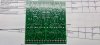
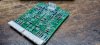
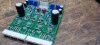
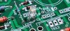
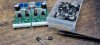
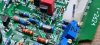
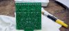
I’ll begin with some photos of the parts and blank PCB and update as the build progresses.

Feel free to chime in with your experience building the ToliTom’s F-2624.

20220514_101732.jpg 20220514_101748.jpg 20220514_101754.jpg Inked20220514_095520_LI.jpg
 
Last edited:
Register to hide this ad
Subscribed :lurk:

The Tom and Toli board is superb. Have one in my 8080db and once installed and set has never again needed any adjustment, rock solid and stable through several years of daily use. Those Toshiba transistor subs look suitable, in fact I have a stash of them on hand as replacements if I run out of the 2690 and 1220's.
I keep wistfully hoping the T's would order a run of blank boards again, their board is that good.
 
Great boards, wish they didn't use the STV-H3 especially since there's a a version that uses a transistor for bias control.
 
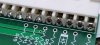
This board is a pleasure to work with and you can see great care has been taken in the design to to ensure component orientation is correctly labled and where possible, dual lead spacing.

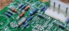
Resistors and Molex header/footers installed. Care taken to ensure all double-sided joints are 'wet' both sides, especially with the footers.

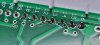
There are many tiny pass-throughs on this PCB (without components) but they do not appear to need pinning as no solder pads present. Technology has come a long way since Sansui's initial run of double-sided boards.

Speaking of, I'm retaining the component legs for an upcoming QRX-9001 project where I'll be repinning the Dolby board, as I have done on this 8080DB.

20220520_104255.jpg 20220520_104303.jpg 20220520_113244.jpg 20220520_145521.jpg 20220520_163014.jpg 20220520_163027.jpg
 
Last edited:
Diodes: including LED-1/2 installed. Note: cathode of LEDs to centre of board (to the bias trimers VR-3/4).

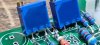
Trimmers: I chose to use Bourns 25-turn trimmers angled slightly to allow for better access with the trimmer adjustment tool. EDIT: SET BIAS TRIMMERS TO MIN RESISTANCE

You may get away with 100ohm max value trimmers for the bias as 200ohm seems a little high from the testing I've done. This will of course depend on the components used but in my case 100ohm should be ample as 30mA is achieved at approximately 20ohms on the trimmers.

Electros: Input caps C-01/02, originally Muse ES bipolar, have been replaced with WIMA MKS2 stacked polyester, with a slight lead mod. C-09/10 the Nichicon KA series were subbed for Panasonic FM due to stock availability. I may sub C-07/08 Nichicon KL caps for PW series in future builds, for no particular reason other than I'm used to working with them for PS applications.

Ceramics installed. Thanks T's for the lead spacing foresight!

Although I'm sure it isn't necessary on these boards (with quality pass-throughs), I am being pedantic with the double-sided soldering where possible :)

Next up heatsinks, drivers, pre-drivers and diffential input pairs.

20220522_100133.jpg 20220522_100533.jpg 20220522_103314.jpg 20220522_103508.jpg 20220522_104719.jpg 20220522_092920.jpg
 
Last edited:
Transistors:

I decided to run with the ON Semi pre-drivers for TR-05-08 as I have stock of the now obsolete KSA1220AY and wanted to keep this build as close as possible to the T's design. For the next 2 F-2624 builds, coming soon, I will try the Toshibas. I've also ettempted to match hFE as best I can with the stock to hand. Not necessary at all really but as I have the numbers, it doesn’t hurt, especially in the input pairs.

hFE of installed BJT listed below just before the part number.

TR-11 Transistors NPN BJT 8A 250V 50W NPN 98 MJE15032G
TR-12 Transistors NPN BJT 8A 250V 50W NPN 97 MJE15032G
TR-13 Transistors PNP BJT 8A 250V 50W PNP 183 MJE15033G
TR-14 Transistors PNP BJT 8A 250V 50W PNP 185 MJE15033G
TR-05 Transistors PNP BJT PNP Epitaxial Sil 210 KSA1220AYS
TR-06 Transistors PNP BJT PNP Epitaxial Sil 210 KSA1220AYS
TR-07 Transistors NPN BJT NPN Epitaxial Sil 210 KSC2690AYS
TR-08 Transistors NPN BJT NPN Epitaxial Sil 210 KSC2690AYS
TR-15 Transistors NPN BJT NPN Epitaxial Sil CBE 284 BC546BTF
TR-16 Transistors NPN BJT NPN Epitaxial Sil CBE 284 BC546BTF
TR-17 Transistors PNP BJT PNP Epitaxial Sil CBE 293 BC556BTF
TR-18 Transistors PNP BJT PNP Epitaxial Sil CBE 294 BC556BTF
TR-01 Transistors NPN BJT NPN Super E-Line CBE 645 ZTX694B
TR-02 Transistors NPN BJT NPN Super E-Line CBE 618 ZTX694B
TR-03 Transistors NPN BJT NPN Super E-Line CBE 644 ZTX694B
TR-04 Transistors NPN BJT NPN Super E-Line CBE 620 ZTX694B

20220522_114514.jpg 20220522_114859.jpg 20220522_120526.jpg 20220522_120537.jpg 20220522_133015.jpg 20220522_134348.jpg 20220522_135329.jpg 20220522_142846.jpg 20220522_142852.jpg 20220522_142912.jpg
 
Last edited:
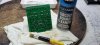
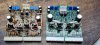
Old vs new board. Chalk and cheese! A very welcome project T's! It really is impressive just how many components are on a board of this size and no floating jumpers!

Something I learnt from Skippy124 (from memory!) was to keep biasing simple by installing a 1ohm resistor across an open cartridge fuse and measuring the bias current in mV instead of mA. Saves polarity dramas and blown DMM fuses. 1mA = 1mV as per Ohm's law.

The board was very easy to dial in and was built right first time. I retained the original Sanken outputs and initial bias was around 250mA with the trimmers set to centre, on DBT of course. Promptly trimmed them back to around 16mA on DBT then to full power, which brought them up to around 25mA Set to 30mA then trimmed the DC to within a millivolt or two of zero.

However, the LEDs were glowing brightly as in photo, which is not ideal and as per my discussions offline with Toli, would be stealing current away from the amp. I will have to experiment with future Tolitoms F-2624 builds to find a more suitable LED. For now, I simply removed the LEDs and re-adjusted bias and DC. I like the idea of the LED as an extra level of output protection and indication of too much current, so will try to come up with a solution.

Protection relay clicked closed, so all good there and I was able to measure DC from the terminals.

20220522_150622.jpg 20220523_084834.jpg 20220523_090347.jpg 20220523_090353.jpg 20220523_091131.jpg 20220523_084332.jpg
 
Last edited:
But, no sound!

Prior to this thread, I’d already restored the frontend (Dolby pins etc.) and tested separately on another power amp, so I knew the issue had to be backend related.

Poking around with my plastic trimmer tool, I found issues with the pre-main ribbon (film) cable that connects the RCA sockets to the preamp board.

After some resoldering attempts, it appears the issue is broken track(s) inside the cable, which are not visible. I decided to remove the entire RCA rear assembly completely, housing 12 sockets. Sansui used 6 plastic rivets to secure the input base plate to the chassis. Great for installation (no room to secure nuts under the ribbon cable) but a little tricky to remove as they are bonded with adhesive. I find the cosmetic acetone based nail polish remover is ideal for softening the glue and enabling the pin to be pushed out. Pure acetone is too strong and will melt the plastic rivets.

I turn the amp on its rear heatsink to allow gravity to keep the fluid where I need it and dab it on with cotton buds (qtips!). I leave it sit for at least 15 minutes, ensuring I keep the rivets wet. In this case, I had to repeat the process once the rivet tips were removed, so I could remove the outer rivet piece. An IC removal tool was handy for pulling the little rivets, as I'm all thumbs! Patience required :boring:

I removed the 2 screws securing the right side of the rear plate to the chassis which allowed a little more room for removal of the inputs and ribbon cables.

Next step is to replace the flimsy film cable with something a little more robust.

20220523_095111.jpg 20220523_102551.jpg 20220523_102602.jpg 20220523_102618.jpg 20220523_110239.jpg 20220523_111612.jpg 20220523_111633.jpg 20220523_111625.jpg
 
Last edited:
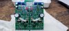
Resolved and what a sweet sound!

I created a simple solution using breadboard ribbon jumpers as they already have a pin for the PCB side. Not as pretty as the Sansui originals but certainly functional. Thanks to everyone who helped out on this thread and in messages to me. I hope this will be useful to others.

Once again, huge shout out to the T's for their efforts in creating this board!

20220523_140826.jpg 20220523_141607.jpg 20220523_151550.jpg 20220523_174930.jpg 20220523_175016.jpg 20220523_200335.jpg 20220523_200401.jpg 20220523_200407.jpg
 
Last edited:
Interesting solution sir. Looks like you were able to change out the caps under the selector switch as well. Not bad getting the old ones out, getting the news ones back in is another deal entirely :)
 
Running this in, it continues to blow me away, especially the Dolby FM and super-silent, transparant phono stage. What a beautiful receiver. Well worth the effort.
Just the wooden case to finish off but the unit has been fully restored internally.
I do plan on sharing the full restoration at some stage when I have time to write it up properly :music:


20220525_180126.jpg 20220525_194328.jpg
 
Back
Top Bottom