

You are using an out of date browser. It may not display this or other websites correctly.
You should upgrade or use an alternative browser.
You should upgrade or use an alternative browser.
Toshiba SA-725 lost FM output
- Thread starter Ace Audio
- Start date

WSideWitness
Active Member
Very low voltage to a few pins. I tried a 2nd multimeter and got the same result. I just grounded the COM lead. Am I supposed to measure between 2 components on the PCB?
WSideWitness
Active Member
Will do. What should my settings be, speakers, antenna, etc? And THANK YOU!
WSideWitness
Active Member
2mV, 500mV, 500mV

Ylli
Super Member
Only thing important for the above was that the receiver was plugged in and turned on. Just to confirm the meter for the above was set to "DC Volts", and the meter common lead was on chassis ground.
Find F902 and D902. Set the meter to "AC Volts". Measure the AC voltage on each side of F902. If the fuse holder does not allow easy access to the fuse ends, then measure for AC volts on the anode end (left side in the attached) of D902. You should see about 12 VAC at all of these points.
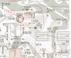
Find F902 and D902. Set the meter to "AC Volts". Measure the AC voltage on each side of F902. If the fuse holder does not allow easy access to the fuse ends, then measure for AC volts on the anode end (left side in the attached) of D902. You should see about 12 VAC at all of these points.
WSideWitness
Active Member
Yep DC volts on the ICs and transistors. Both sides of F902 and D902 anode measure 13.4V AC.
I really feel like I'm missing something easy. I'm no wizard with electronics, but I'm no dummy either
I really feel like I'm missing something easy. I'm no wizard with electronics, but I'm no dummy either
WSideWitness
Active Member
Would a bad cap at C905 cause these symptoms? I have an ESR meter coming next week
Ylli
Super Member
If you have 13.4 VAC on the anode of D902 and no DC on the cathode (Also Q901 collector) then D902 must be bad.
If C905 was open, you would still have DC on the collector of Q901, although it would measure lower and have a lot of 60 HZ ripple on it. If C905 was shorted, F902 would have blown. Looks like nothing is getting though D902. Pull the part from the board and check it with the 'diode' function on your meter. It should show open in one direction and about 0.6 in the other direction. A 1N4002 diode would be an easy to get replacement.
If C905 was open, you would still have DC on the collector of Q901, although it would measure lower and have a lot of 60 HZ ripple on it. If C905 was shorted, F902 would have blown. Looks like nothing is getting though D902. Pull the part from the board and check it with the 'diode' function on your meter. It should show open in one direction and about 0.6 in the other direction. A 1N4002 diode would be an easy to get replacement.
WSideWitness
Active Member
Will do. You are amazing sir! Where would you point a guy like me that loves fixing these old things but has only very basic knowledge and a lack of fear. I'd like to be able to read a schematic well and pinpoint problems.
WSideWitness
Active Member
Well I appreciate anyone who is willing to help out strangers like you do. I started this hobby 9 months ago and I've learned a ton already. I just don't want to rely on the kindness of others too much or eventually it will run out. Hence the desire to educate myself as much as possible. I'll update after I get a new diode in
WSideWitness
Active Member
I just removed D902 and it tests good! OL one direction and ~0.6V when reversed. Is there any chance it actually is bad but tests good? I'll replace it with a new one anyway since I pulled it, but it doesn't seem that is the problem.
Ylli
Super Member
That's why I said what I said in post #51. Did you measure for the DC voltage on the cathode of D902 or on the collector of Q902? There may have been or may still be a bad solder connection on the board, or a cracked run. Measure the AC voltage on the pad where you removed the anode of D902 (left side in the pix I sent). You should still see that 13.4 VAC on that pad. Replace the diode (watch for correct polarity). Check for DC voltage right on the cathode lead of D902. Anything?
WSideWitness
Active Member
Well you were definitely on the right track because I put D902 back in and AM/FM are working. Must've been a bad solder joint. I retested all points on Q101 Q102 Q103 Q201 Q901. Everything tests good except for a few points that I'll list in the image below. Only issue now is that FM muting as well as signal & tuning meters don't work.

Attachments

WSideWitness
Active Member
Just reread the thread and I'm going to try what was mentioned in post #23
Ylli
Super Member
On your chart, you measure Q103 pin 12 at 5.6 volts and pin 15 at 6.0 volts. That should provide some deflection on the tuning meter. Are you getting any?
Go ahead and adjust T101 for the same voltage on Q301 pins 12 and 15.
Q103 pin 1, 3.7 volts probably OK.
Pin 3 is AGC when in AM mode, and is also used to disable the AM IF when in FM mode. I suspect if you switch to AM that voltage will come up.
Pin 10 is the mute voltage - It may be right on the edge of muting. Fully muted that pin would be near zero and unmuted close to 5 volts.
Before we look at the FM Stereo decode chip (Q201), let's see if we can get the AM section fully working. We should be getting some signal strength meter defletion when tuning through stations.
Go ahead and adjust T101 for the same voltage on Q301 pins 12 and 15.
Q103 pin 1, 3.7 volts probably OK.
Pin 3 is AGC when in AM mode, and is also used to disable the AM IF when in FM mode. I suspect if you switch to AM that voltage will come up.
Pin 10 is the mute voltage - It may be right on the edge of muting. Fully muted that pin would be near zero and unmuted close to 5 volts.
Before we look at the FM Stereo decode chip (Q201), let's see if we can get the AM section fully working. We should be getting some signal strength meter defletion when tuning through stations.
WSideWitness
Active Member
Pins 12 & 15 now match when a stereo signal is tuned in. Tuning & signal meters still aren't working. No movement at all. FM muting works not great but mostly ok. The only pin that may be out of spec is 9. Here's my current measurements.

Ylli
Super Member
Pin 9 will be a DC voltage based on FM signal strength. It makes sense that it is high on FM and near zero when set to AM. You might notice the voltage is a bit different on weaker FM stations than on stronger FM stations. With that point at 4.2 volts, that should push about 150 uA through the signal strength meter. The parts list does not indicate the meter sensitivity, but I would think 150 uA should produce significant deflection. Closer look at the HA11211 data sheet shows typically 4.4 volts on pin 9 with a strong signal input. Might want to measure the voltage on either end of R124 when tuned to a strong FM signal.
I've got a few very busy days coming up, I may be a bit slow in responding.
I've got a few very busy days coming up, I may be a bit slow in responding.
WSideWitness
Active Member
Pin 9 does vary based on FM signal strength. The strongest signal produces about 4.4VDC and lowers when the signal is weaker.
I measured R126 D108 R124. All varied depending on signal strength
R126 = 1.9V-3.9V / 110mV-230mV
D108 = 2.2V-4.4V / 1.9V-3.9V
R124 = 100mV-240mV / 78mV-182mV
I hope you can make sense of this. All solder connections look good, but I may touch them up to make sure.
I measured R126 D108 R124. All varied depending on signal strength
R126 = 1.9V-3.9V / 110mV-230mV
D108 = 2.2V-4.4V / 1.9V-3.9V
R124 = 100mV-240mV / 78mV-182mV
I hope you can make sense of this. All solder connections look good, but I may touch them up to make sure.