
Ylli
Super Member
Good for you. It's a worthy goal for all of us.Just want to explore and learn.


Good for you. It's a worthy goal for all of us.Just want to explore and learn.
No worries, no opened cans of worms. Even perfectly matching on a curve tracer doesn't guarantee they'll remain matched over time. As long as DC offset is within reason, it doesn't really hurt anything anyways. When I rebuilt my Sansui 7070, I "only" hFE matched the 4 input transistors (1 pr ZTX694B each channel) and to my surprise, the DC offset holds steady at 0mV in both channels. Unheard of in one of these.Not to open a can of worms here.... Ideally, you want to match both hFE and Vbe. If your goal is to minimize DC offset, then I think Vbe will be more important. hFE will affect offset even with perfectly matched Vbe's, but it is a secondary effect created by the base currents in the base resistors.
 But I don't expect it to be quite the same a year later.
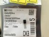
The leads are plenty long enough. However notice the old transistor is center Base, and the new one center Collector. You'll have to twist those leads.One more question, trying to replace C1124 on this same unit since it is on the top ten worst transistors. The replacement will be ksc2690 based on what I read here. But when I look at these C1124 on the heat sink closer, they actually has a small metal plate extension on top end of the transistor (red arrow) then mounted onto a filler (blue arrow) on top of the heat sink. The new ksc2690 actually does not have the metal plate extension, so I just mount it directly onto the filler with the screw, and the transistors will be much higher, not quite sure the legs going to long enough?
View attachment 2028543 View attachment 2028544
And you can pull the heat sink to drill a lower hole if necessary, but I doubt you will need to.One more question, trying to replace C1124 on this same unit since it is on the top ten worst transistors. The replacement will be ksc2690 based on what I read here. But when I look at these C1124 on the heat sink closer, they actually has a small metal plate extension on top end of the transistor (red arrow) then mounted onto a filler (blue arrow) on top of the heat sink. The new ksc2690 actually does not have the metal plate extension, so I just mount it directly onto the filler with the screw, and the transistors will be much higher, not quite sure the legs going to long enough?
View attachment 2028543 View attachment 2028544
Remove the old transistor. Then with the new transistor and the writing facing you, the pinout is E C B. E is the left. So you twist the Center (Collector), and the Right (Base) lead, then bend them to align with the holes on the board using the underside (foil side) as an easy to reach pattern to follow. Then making sure the leads are not touching, do a "dry fit" on the heat sink and see where the leads land. Do not bend the leads back and forth much or they will break. They are plated brass and pretty soft. If they fit with enough sticking through to solder, and the screw is in place where the transistor will be, all that is left is to put a dab of thermal compound on, then screw it to the heat sink. Then solder and you're done. If you feel the 2 crossed leads are "too close" to each other, strip a piece of wire (if you have any) and use the stripping as an insulating tube on the center lead. If the leads are too short, or don't stick through enough, then go ahead and drill a new mounting hole in the heat sink.Thanks for pointing that out. The holes on the board are pretty spread apart, with the twisted legs I probably need to drill a lower mounting hole. Those 3 holes are pretty much in the same line, it seems tricky to twist the legs and at the same time to be mounted on the heatsink, any tips?
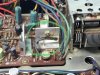

Yes, it needs to sense the heat so glue it back on. I use a high temperature adhesive used in clothes dryers, and just a dab, but any "high temperature glue" will work. Now I am not talking about "extreme" temperatures like in furnaces or refractories. Some people use a dab of electrical grade silicone. Electrical grade silicone doesn't have acetic acid and won't attack aluminum. And it also doesn't have that pungent odor.@Skywatcher, thanks a lot for the detailed instruction, will do.
Another question is there is also an “R645” with black wires and transparent film wrap glued to the back side of this particular heatsink, any idea what this is for? And do I need to maintain it glued to the heatsink after replacing the front transistor c1124?
View attachment 2028667 View attachment 2028668
How about you start your own thread specific to your unit so we don't clog this one up.@Skywatcher, thanks a lot for the detailed instruction, will do.
Another question is there is also an “R645” with black wires and transparent film wrap glued to the back side of this particular heatsink, any idea what this is for? And do I need to maintain it glued to the heatsink after replacing the front transistor c1124?
View attachment 2028667 View attachment 2028668

these C1124
Remove the old transistor. Then with the new transistor and the writing facing you, the pinout is E C B. E is the left. So you twist the Center (Collector), and the Right (Base) lead, then bend them to align with the holes on the board using the underside (foil side) as an easy to reach pattern to follow
The free standing ones aren't all that bad since they are "free" and you can give the whole transistor a twist to keep the leads apart. The ones on a heat sink is where the real PITA can be.those Sony transistors with center base are a PITA to replace. Leg twisting of the replacements is unavoidable.
Please start your own thread for your unit.Need to find substitution of 2SC734 for a power supply board on my Onkyo TX 560 receiver, is that KSC1845 or KSC1815 or something else? Thanks.
Starting your own thread allows us to help with your specific unit instead of causing confusion in an already existing thread.Did report my post and hopefully someone will remove it. Thx.


https://www.mouser.com/ProductDetai...SA733GTA/?qs=sGAEpiMZZMvAvBNgSS9LqsiT6VxBgG5EThis thread suggests a few substitutions for 2SA733, but I can only find one stocked, which is KSA992. While searching around, I may have found another potential replacement, but I would like some opinions about it, in case I am missing something (my solid-state-fu is weak.) The potential replacement is BC556A. A table is below to help with comparisons; it includes specs for the original, a couple suggested replacements, and this potential sub. Thanks for any comments or other suggestions.
RATING 2SA733 KSA733 KSA992 BC556A
====== ====== ====== ====== ======
VCEO -50 -50 -120 -65
VCBO -60 -60 -120 -80
VEBO -5 -5 -5 -5
hFE 200 240 200 220
fT MHz 100 180 100 150
Ic mA 100 150 50 100
Pd mW 250 250 500 500
Specific application: speaker protection board
Pinout. The BC556A is center base instead of center collector.This thread suggests a few substitutions for 2SA733, but I can only find one stocked, which is KSA992. While searching around, I may have found another potential replacement, but I would like some opinions about it, in case I am missing something (my solid-state-fu is weak.) The potential replacement is BC556A. A table is below to help with comparisons; it includes specs for the original, a couple suggested replacements, and this potential sub. Thanks for any comments or other suggestions.
RATING 2SA733 KSA733 KSA992 BC556A
====== ====== ====== ====== ======
VCEO -50 -50 -120 -65
VCBO -60 -60 -120 -80
VEBO -5 -5 -5 -5
hFE 200 240 200 220
fT MHz 100 180 100 150
Ic mA 100 150 50 100
Pd mW 250 250 500 500
Specific application: speaker protection board