

You are using an out of date browser. It may not display this or other websites correctly.
You should upgrade or use an alternative browser.
You should upgrade or use an alternative browser.
Trouble shooting silicon rectifier diodes in power supply.
- Thread starter HowardK
- Start date
Register to hide this ad

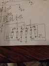
No part numbers there, also not quite sure that arrangement looks right but if its under 1 amp and 1kv peak inverse voltage, which it probably is for a 6bq5 amp, I'd guess a 1n4007 or similar would get it done.
Fairly unlikely a failed diode would have anything to do with any problem you're having here. When rectifiers go either you get low voltage when it goes open or high ripple when it shorts.
Fairly unlikely a failed diode would have anything to do with any problem you're having here. When rectifiers go either you get low voltage when it goes open or high ripple when it shorts.

ok that makes more sense. Its a bridge, and then half a bridge. Full current through the two diodes going to ground, half through each pair with a + output. Exactly why they did this is unknown but at least I understand it now.
what would you even call half a bridge? A plank?
what would you even call half a bridge? A plank?
The jumping point!!ok that makes more sense. Its a bridge, and then half a bridge. Full current through the two diodes going to ground, half through each pair with a + output. Exactly why they did this is unknown but at least I understand it now.
what would you even call half a bridge? A plank?

maxhifi
Addicted Member
Might need to see the whole schematic, and also need a better understanding of what "has 16 watts dissipation on the right channel of a 6bq5 power tube." means.I located a schematic. Some one evidently removed three resistors the 150k on the schematic are they were never installed.
Yes single ended with a headphone amp and a precut.Is it a single-ended amp?
This 6-diodes power supply is unusual for a 6BQ5 amp.
I dont know if its legal to post the schematic. Well the right channel 6bq5 is running around 65 milliamps.Might need to see the whole schematic, and also need a better understanding of what "has 16 watts dissipation on the right channel of a 6bq5 power tube." means.

Yes single ended with a headphone amp and a precut.
My guess is that the full-wave bridge is for the B+ voltages (the anodes of the tubes). The two-diode rectification is for the screen voltage.
The entire schematic would prolly tell it all.

The output of the two sets of diodes should be the same voltage since they have the same AC input and filtering setup. If they are actually different, I suspect there is some other problem. Open filter cap maybe, that makes for low voltage.
Seems more likely two plate supplies with the idea to isolate it per-channel. I'm guessing the 150K are bleeder resistors since they can't pass meaningful current at those voltages. I'm not going to do the math but at a glance I can tell you its a bit over 1mA to ground from each supply, and considerably less between them.
Seems more likely two plate supplies with the idea to isolate it per-channel. I'm guessing the 150K are bleeder resistors since they can't pass meaningful current at those voltages. I'm not going to do the math but at a glance I can tell you its a bit over 1mA to ground from each supply, and considerably less between them.
Yeah, what an odd way to make a rectifier setup. A complete schematic is needed to avoid speculation.The output of the two sets of diodes should be the same voltage since they have the same AC input and filtering setup. If they are actually different, I suspect there is some other problem. Open filter cap maybe, that makes for low voltage.
Seems more likely two plate supplies with the idea to isolate it per-channel. I'm guessing the 150K are bleeder resistors since they can't pass meaningful current at those voltages.
maxhifi
Addicted Member
I dont know if its legal to post the schematic. Well the right channel 6bq5 is running around 65 milliamps.
If the tube is running too hot, and you have tried another tube, then it's to do with the way the output tube is biased. Could be a failed coupling capacitor, could be a failed or failing bias supply if fixed bias, etc. It's a guessing game without seeing the whole schematic, and I have no reason to believe that it's the diodes you have shown causing the issue.
A complete schematic is needed to avoid speculation.
Agreed
Posting a schematic will be fine. Really, it's the only way to figure out the idea behind the diode setup in the power supply.I dont know if its legal to post the schematic. Well the right channel 6bq5 is running around 65 milliamps.
65mA for a pair of EL84? If the plate voltage is around 330 VDC, that would be about 21.5 W per pair, which would be in the upper range of Class AB1, but fine. If it's 65mA per tube, that's way too hot.
You need the plate voltages on those EL84 tubes, along with the idle bias current, to calculate the idle watts.


Al Casey
Active Member
Otherwise, the manufacturer's model number would be helpful.If the tube is running too hot, and you have tried another tube, then it's to do with the way the output tube is biased. Could be a failed coupling capacitor, could be a failed or failing bias supply if fixed bias, etc. It's a guessing game without seeing the whole schematic, and I have no reason to believe that it's the diodes you have shown causing the issue.
Agreed
If the three 150 k resistors were never installed, did this amplifier work?
It's perfectly legal to post schematics
Al Casey
Active Member
Based on the information provided in this partial schematic, it seems to me that two rectifier diodes are missing from the channel receiving 330 V, and that the three 150 k resistors are used to automatically balance the B+ voltage of each channel.
There is a 70 V difference between the two channels, which is enormous.
I could be wrong.
There is a 70 V difference between the two channels, which is enormous.
I could be wrong.