• The move to the new server is done. There are some software and database maintenance updates in process. This has us passing the hat around to help out. We appreciate any donations. Seriously, even a dollar helps. The payment page may be found here - https://www.audiokarma.org/support.html

Trouble shooting silicon rectifier diodes in power supply.

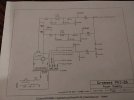
Based on the information provided in this partial schematic, it seems to me that two rectifier diodes are missing from the channel receiving 330 V, and that the three 150 k resistors are used to automatically balance the B+ voltage of each channel.
There is a 70 V difference between the two channels, which is enormous.
I could be wrong.
That can't be right. Another WAG is that the 330VDC line goes to the input/gain/phase inverters. And the 400VDC goes to the EL84s.

But, I'm just pulling hairs out of my hindsight. ;)
 
it'll work as-drawn. Its not really missing a set of diodes exactly, just two of them are carrying double the current of the other four. Its absolutely goofy looking, but perfectly functional now that I really understand what they are doing here.

just to show you what I mean, this is what it would look like with two traditional full wave bridges

1787695498686.png

however that is electrically equivalent to this
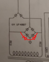
1787695672218.png

there wouldn't really be any point to doing that, other than to divide up the current flow. A UF4007 is good for an amp, and you couldn't make a 6bq5 flow an amp if lightning struck the thing. The two diodes tied to ground will each carry 2x the load of the diodes going up towards the filter caps, but its well within their capabilities.


also that voltage can't be different unless something is wrong. The 150K resistors won't have anything to do with it. Those function as bleeder resistors, about all that would happen if they are missing is the supply won't drain down correctly. Less than optimal, but also not really a big deal. Tons of things were made without bleeder resistors and they still function.

my best guess is bum filter cap, or maybe one open diode, though I'd have guessed more than 70v difference. It would have to be one of the two upper diodes in the schematic if its going to be one of those.

the high dissipation I'll agree is probably a leaky cap or badly selected bias point.

No idea what we're working with here but some of the offshore tube designs are not exactly properly designed and may need tweaking to actually function correctly.

 
The original schematic is an odd way to draw up a bridge with diodes in parallel. I was taught not to parallel smaller diodes to increase the current flow. It's better to use properly rated single diodes. Especially since higher amp-rated diodes are readily available.

There's still something very wrong with this setup. I presume it's an EL84 push-pull stereo amp (headphone amp)? I still don't have any idea what the model is.

A quad of EL84 output tubes should not need anything more than a good 1N4007, 1-amp full-wave bridge for the B+. No paralleling of diodes should be needed.


:idea:
 
Last edited:
True, and thats also probably why there are only 2 to ground. The slightly mismatched junction voltages means they don't really share like it seems they ought to, one does everything, the other does nothing.

splitting the + side will give channel to channel isolation, not that its really needed but I guess someone was concerned about cross-talk?
 
True, and thats also probably why there are only 2 to ground. The slightly mismatched junction voltages means they don't really share like it seems they ought to, one does everything, the other does nothing.
Yeah, if you need a more current from the power supply, go to the 1N540X (or UF540X) series diodes. Never parallel these things. You are asking for problems.

This, of course, has to match the PT specs and the rest of the power supply's caps and resistors.

:)
 
Last edited:
The original schematic is an odd way to draw up a bridge with diodes in parallel. I was taught not to parallel smaller diodes to increase the current flow. It's better to use properly rated single diodes. Especially since higher amp-rated diodes are readily available.

There's still something very wrong with this setup. I presume it's an EL84 push-pull stereo amp (headphone amp)? I still don't have any idea what the model is.

A quad of EL84 output tubes should not need anything more than a good 1N4007, 1-amp full-wave bridge for the B+. No paralleling of diodes should be needed.


:idea:
He said it’s a single-ended amp.
 
OK guys here it is. Right channel runs 65 ma and left channel runs 51 ma. Right channel is higher throughout because the HV voltage is about 70 volts higher.
 

Attachments

  • 20260825_201800.jpg
    20260825_201800.jpg
    68.2 KB · Views: 44
  • 20260825_201740.jpg
    20260825_201740.jpg
    70.6 KB · Views: 42
The amp i have is no.12 and used different diodes as noted in the schematic. He changed to uf4007 in 2013. I don't know what's in there now as I can't make them out. I will have to order some uf4007 to put in there.
 
Thanks for the schematics. I cleaned and enlarged them.

3ef4324e-1e36-412e-a59f-a30d1f46f593.jpg


41efade7-d8fb-4b02-ace7-f7cd8a05e107.jpg


It's odd how the two diodes on the top are wired like a two-diode full-wave bridge, but the PT has no center tap. :idea:

We need to ask Alan Kimmel about this. :)
 
Back
Top Bottom