

You are using an out of date browser. It may not display this or other websites correctly.
You should upgrade or use an alternative browser.
You should upgrade or use an alternative browser.
Trouble shooting silicon rectifier diodes in power supply.
- Thread starter HowardK
- Start date

whoaru99
Epic Member
Here are voltages.
Except for the AC 330Vrms secondary, all other DC voltages are measured with respect to the exact same chassis ground point?
whoaru99
Epic Member
408vdc sounds about right for that with a resistor between the diodes and the first cap, the 341 volts seems low to me.
current flow on the right channel seems too high.
Yeah, liberties taken with some values (constant 50mA load per channel, secondary resistance, etc.) but I tend to agree.
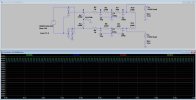
Playing around in LT Spice I ended up with
(green) 409 @ point A
(blue) 406 @ B
(red) 331 @ C
(yellow) 310 @ D
Happy to tweak it if there are suggestions.
Last edited:

maxhifi
Addicted Member
just for yucks, if you lift one diode on the + output side in LTSpice, does it drop to ~330vdc ?
I think you figured it out.. gotta be that
whoaru99
Epic Member
Doesn't drop that much in Spice. It goes to 20V difference between the two.just for yucks, if you lift one diode on the + output side in LTSpice, does it drop to ~330vdc ?
If I pull one of the - side diodes it drops 35V, but both sides drop, not just one.
I think it's an avenue to purse though. Maybe some difference between the real deal and model exacerbates the difference. Sketchy solder joint, maybe?

@Howard, sorry if this was already answered, but what are the voltages on each channel's EL84 anode plate? What is the idle bias current (voltage drop) across each channel's cathode-tied resistor?
Just to find the amount of power imbalance on each channel. Then, work backward to find the cause.
Thanks!

Left plate 232vdc -6.6 vdc = 225.4 = 49.3 ma, 11.1 watts@Howard, sorry if this was already answered, but what are the voltages on each channel's EL84 anode plate? What is the idle bias current (voltage drop) across each channel's cathode-tied resistor?
Just to find the amount of power imbalance on each channel. Then, work backward to find the cause.
Thanks!
Right plate 272vdc -7.8vdc = 264 = 58.2 ma, 15.4 watts
I am including the output trans resistance which total to 134 ohms
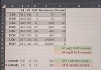
Left plate 232vdc -6.6 vdc = 225.4 = 49.3 ma, 11.1 watts
Right plate 272vdc -7.8vdc = 264 = 58.2 ma, 15.4 watts
I am including the output trans resistance which total to 134 ohms

If you pull the EL84 tubes, are the plate voltages on the right-to-left channel still far off?
If you swap EL84 tubes between the left and right channels, do the wattage values remain the same? Or follow the tubes?
I asked because sometimes tubes can draw more current, causing a voltage drop on that side. Just to rule this out.
Is the resistance of the cathode-tied resistors within 5-10% of each other?
Thanks again!
Yes yes and yes
If you pull the EL84 tubes, are the plate voltages on the right-to-left channel still far off?
If you swap EL84 tubes between the left and right channels, do the wattage values remain the same? Or follow the tubes?
I asked because sometimes tubes can draw more current, causing a voltage drop on that side. Just to rule this out.
Is the resistance of the cathode-tied resistors within 5-10% of each other?
Thanks again!
Thanks!Yes yes and yes

You were correct. The imbalance between channels prolly lies in this power supply. I can't wrap my head around the rectifier bridges and why they seem to guarantee a voltage difference between the channels.
And I have not seen the 150k/150k ohm voltage divide, with a 150k ohm to ground in a power supply before. It looks kinda like a bleeder setup of some sort.

Sorry, I'm just throwing stuff at the wall now. Does Alan Kimmel still answer emails?
The Lansing Heritage reference to him.

They shouldn't guarantee a voltage difference. It ought to be the same.
Its still a standard bridge rectifier electrically speaking.
basically its this

plus this
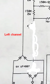
or another way it could be done is like this

these would all be pretty equivalent, its really just a bridge rectifier with diode isolation between the two channels.
Its still a standard bridge rectifier electrically speaking.
basically its this
plus this
or another way it could be done is like this
these would all be pretty equivalent, its really just a bridge rectifier with diode isolation between the two channels.
Well, there's a problem. His (L and R) voltages are way off each other. Even with the EL84 tubes removed (post #72).They shouldn't guarantee a voltage difference. It ought to be the same.
Its still a standard bridge rectifier electrically speaking.
basically its this
View attachment 3825280
plus this
View attachment 3825283
or another way it could be done is like this
View attachment 3825290
these would all be pretty equivalent, its really just a bridge rectifier with diode isolation between the two channels.
I checked it a couple of days ago with all tubes pulled and the imbalance was still there only higher. Slightly above the capacitor ratings so I terminated the test early.What are the voltages with the tubes.
I can hook my brown box up and lower the voltage 9n the amp and test again if you would like me to
Last edited:
Pull all of them. Read the EL84 plate voltages (L and R).With all are just the power tubes?
Then insert the signal tubes, only, and see if there is a change. I doubt it, but just in case.